
Traffic Calming Guidance Resources
Based on engineering judgment, traffic calming strategies should be considered whenever there is a need to reduce vehicle speeds and/or traffic volumes on a roadway or roadway network. These elements are prepared for Caltrans for use on the California State Highway System and it is not a substitute for engineering knowledge, experience, or judgment. The traffic calming measure can be implemented separately or be used in conjunction with other calming measures.
Each traffic calming measure belongs to one of six categories: Signing and Markings, Physical Intersection Modifications, Roadway Narrowing, Vertical Roadway Elements, Physical Roadway Segment Modifications, and Others.
For more information, email Safety Programs.
Resources
- Traffic Calming Guidance (PDF)
- Traffic Calming Guide Training - Recording password: iQ2zkbMa
Traffic Calming Guidance Elements
| SIGNINGS AND MARKINGS |
| Vehicle Speed Feedback Sign |
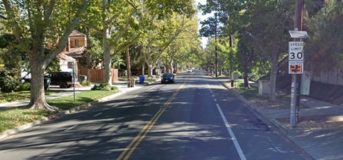 |
| Description: Speed Feedback Signs (SFS), also known as Dynamic Speed Displays, provide drivers feedback about their speed, while reminding drivers of the posted speed limit. |
| Standard Plans: Roadside Signs RS1 | RS2 | RS3 | RS4 | RS5 | RS6 |
| CA MUTCD: Section 2B.13 Figure 2C-1 (does not indicate maximum posted speed limits for this countermeasure) |
| Other Guidance: FHWA Spotlighting Speed Feedback Signs |
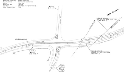
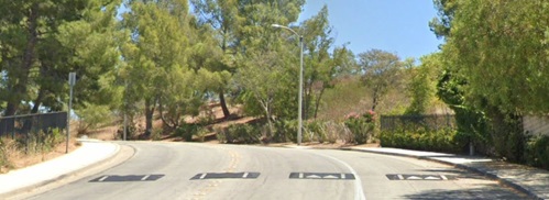
| Speed Reduction Markings |
 |
| Description: Speed Reduction Markins, also known as Optical Speed Bars, are transverse pavement markings placed with progressively reduced spacing on both edges of the traveled way to create the perception of increased speed. This illusion encourages drivers to slow down as they pass by the markings. |
| CA MUTCD: Section 3B.15, Figure 3B-28 | 3B.22 |
| Other Guidance: FHWA Low-Cost Treatments for Horizontal Curve Safety 2016, Chapter 3 |
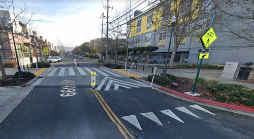
| In-Street Pedestrian Crossing Signs |
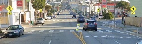 |
| Description: In-street pedestrian crossing signs are placed within a roadway, either between travel lanes or in a median. The sign may be used to remind road users of laws regarding right-of-way at an unsignalized pedestrian crossing. |
| Standard Plans: Signs/Delineators A73A | A73C |
| CA MUTCD: Section 2B.12, Figure 2B-1, Table 2B-1 | Section 7B.12, Figure 7B-6 |
| Other Guidance: FHWA Proven Safety Countermeasures - Crosswalk Visibility Enhancements |
| Crosswalk Enhancements |
 |
| Description: Crosswalk enhancements include high-visibility crosswalk markings and marking patterns, improved lighting, advance stop/yield/pedestrian crossing markings and signs, parking restrictions, curb extensions, raised crosswalks, rectangular beacons (RRFB), and pedestrian hybrid beacons. |
| Standard Plans: Crosswalks A24F | Roadside Signs RS1 | RS2 | RS3 | RS4 | RS5 | RS6 | APS Push Buttons ES-5C |
| CA MUTCD: Section 2B | 3B.16 | 3B.18 | Chapters 4E | 4F | 4L |
| Other Guidance: FHWA Field Guide for Selecting Countermeasures at Uncontrolled Pedestrian Crossing Locations | FHWA Guide for Improving Pedestrian Safety at Uncontrolled Crossing Locations | FHWA Proven Safety Countermeasures - Crosswalk Visibility Enhancements |
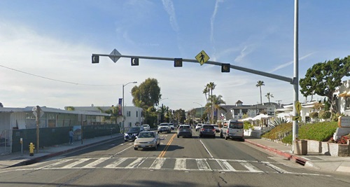
| Pedestrian Hybrid Beacons |
| |
| Description: Pedestrian hybrid beacons (RHBs) are pedestrian-activated overhead signals consisting of two red lenses above a single yellow lens. The lenses remain "dark" until a pedestrian pushes the call button to activate the beacon, which then initiates a yellow to red lighting sequence that directs motorists to slow and come to a stop. |
| Standard Plans: Mounting ES-4E |
| Standard Specs: 87-8 |
| CA MUTCD: Chapter 4F |
| Other Guidance: FHWA Pedestrian Hybrid Beacon Guide | FHWA Proven Safety Countermeasures - Pedestrian Hybrid Beacons |
| Flashing Beacons |
| Description: Flashing beacons use repeated flashing lights to warn motorists of a potential hazard. They are used to draw motorists' attention to a sign informing them of an upcoming change in the road conditions that could include unseen intersections, schools, curves, or other hazards. |
| Standard Plans: Flashing Beacon ES-7J | ES-7K | ES-7L |
| Standard Specs: 87-7 |
| CA MUTCD: Chapter 4L |
| Other Guidance: FHWA Low-Cost Treatments for Horizontal Curve Safety 2016, Chapter 4 |
| PHYSICAL INTERSECTION MODIFICATIONS |
| Roundabouts |
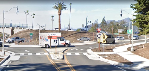 |
| Description: A roundabout is a form of circular intersection in which traffic travels counterclockwise around a central island and entering traffic must yield to the circulating traffic. |
| HDM: Chapter 400, Index 405.10 |
| CA MUTCD: Chapters 2B | 2C | 3C | 6H | 9C |
| Caltrans DIB: 94 |
| Other Guidance: Caltrans Proven Safety Countermeasures Roundabouts | FHWA Traffic Calming ePrimer (3.09) | FHWA Proven Safety Countermeasures | Traffic Operations Policy Directive #13-02 |
| Full Closure |
 |
| Description: Typical full closure implementation can help improve safety by reducing intersection conflict points and cut-through traffic. |
| Standard Plans: Ramp Closure T14 |
| Caltrans DIB: 93 |
| Other Guidance: FHWA Traffic Calming ePrimer (3.22) |
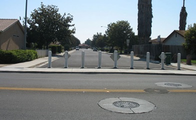
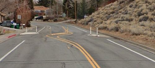
| Intersection Barrier |
 |
| Description: An intersection barrier can be used to limit left-turn movements through an intersection. A fixed barrier such as a curb, raised island, or planter limits vehicle movements through the intersection, forcing drivers to reduce approach speeds. |
| Standard Plans: Curbs A87A |
| HDM: Topic 404 |
| Other Guidance: FHWA Traffic Calming ePrimer (3.24) | ITE Traffic Calming Facts Sheets - Median Barrier |
| Partial Closure/Semi-Diverter |
 |
| Description: Typical partial closure implementation can help improve safety by reducing intersection conflict points and cut-through traffic. |
| Standard Plans: Traffic Control T13A | T13B |
| Caltrans DIB: 93 |
| Other Guidance: FHWA Traffic Calming ePrimer (3.23) |
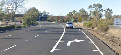
| Right-In, Right-Out |
 |
| Description: Typical right-in, right-out implementation can help improve safety by reducing intersection conflict points, cut-through traffic, and restricting movements that have a higher likelihood of more severe injury crashes. |
| HDM: Topic 404 |
| Caltrans DIB: 93 |
| Other Guidance: FHWA Traffic Calming ePrimer (3.24)| HCM 7th Edition Chapters 4, 15, 25, 35 | ITE Traffic Calming Fact Sheet - Forced Turn Island |
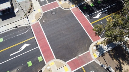
| Tee-up Intersection and Reduce Corner Radii |
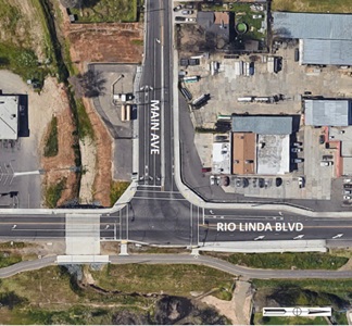 |
| Description: Corner radii directly impacts vehicle turning speeds and pedestrian crossing distances. Minimizing the size of a corner radius is critical to creating compact intersections with safe turning speeds. |
| HDM: Chapter 400 |
| Caltrans DIB: 94 |
| Other Guidance: Caltrans Complete Intersections 2010 | NACTO Urban Street Design Guide, Corner Radii |
| ROADWAY NARROWING |
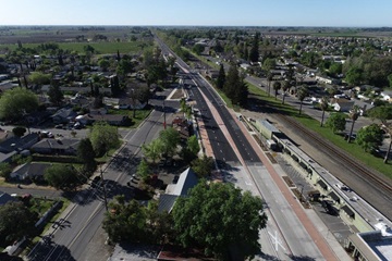
| Road Diet |
 |
| Description: Typical road diets include roadway treatments that reduce the number of travel lanes and/or lane widths in order to address transportation deficiencies. Road diet allows reclaimed space to be allocated for other uses, such as bike lanes, sidewalks, bus islands and shelters, bus lanes, landscaping, pedestrian refuge islands, turn lanes, or parking. |
| HDM: Chapter 300 |
| Caltrans DIB: 94 |
| Other Guidance: FHWA Traffic Calming ePrimer (3.20) | FHWA Road Diet Policies |
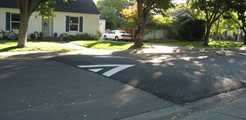
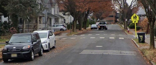
| Neckdowns/Chokers |
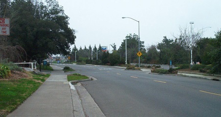 |
| Description: A choker is a horizontal extension of the curb at a midblock of a street resulting in a narrower roadbed section. Other terms for choker include neckdown, midblock narrowing, midblock yield point, pinch point, constriction, or edge island. If the choker is marked with a crosswalk, it is sometimes called a safe cross. |
| HDM: Topic 303, Index 303.4(1) |
| Caltrans DIB: 93 | 94 |
| Other Guidance: FHWA Traffic Calming ePrimer (3.17) |
| Curb Extension/Bulbouts |
 |
| Description: Bulbouts are curb extensions that shorten the crossing distance and provides more area and visibility for pedestrians. |
| Standard Plans: Curbs A87A | Curb Ramp A88A | Temp Ped Ramp T33 | Temp Ped Curb Ramp T34 |
| HDM: Indexes 303.4 | 404.4 |
| Caltrans DIB: 93 | 94 |
| Other Guidance: FHWA Traffic Calming ePrimer (3.16) |
| On-Street Parking |
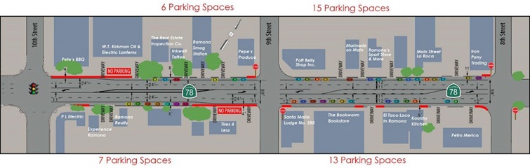 |
| Description: On-street parking can assist in achieving lower operating speeds by constricting driver experience with increased side friction. |
| Standard Plans: Accessible Parking On-Street A90B |
| HDM: Chapter 300 |
| CA MUTCD: Sections 2B.46 | 2B.47 | 2B.48 | 3B.19 |
| Caltrans DIB: 82-06 |
| Other Guidance: AASHTO Highway Safety Manual | FHWA Traffic Calming ePrimer (3.19) | ITE Traffic Calming Fact Sheet - On-Street Parking |
| Raised Median Island/Traffic Island |
 |
| Description: Traffic islands are typically used for channelization but could also be used for traffic calming, since it introduces a curb adjacent to vehicles and has the effect of slowing vehicles. Pedestrian refuge islands and raised median islands are commonly used together. |
| Standard Plans: Island passageway A88B |
| HDM: Topic 405.4, Table 405.4 | Topic 904 |
| CA MUTCD: Sections 2C.63 | 2C.64 | 2C.66 | Chapter 3I |
| Caltrans DIB: 82-06 | 93 | 94 |
| Other Guidance: FHWA Traffic Calming ePrimer (3.18) |
| VERTICAL ROADWAY ELEMENTS |
| Speed Hump |
 |
| Description: A speed hump is an elongated mound in the roadway pavement surface extending across the travel way at a right angle to the traffic flow. |
| CA MUTCD: Sections 2C.29 | 3B.25 | 3B.26 | Figure 3B-30 |
| Caltrans DIB: 93 |
| Other Guidance: FHWA Traffic Calming ePrimer (3.10) | ITE Updated Guidelines for the Design and Application of Speed Humps |
| Speed Cushions |
 |
| Description: A speed cushion consists of two or more raised areas placed laterally across a roadbed. A speed cushion has gaps between the raised areas to enable a vehicle with a wide track to pass through the feature without any vertical deflection. |
| CA MUTCD: Sections 2C.29 | 3B.25 | 3B.26 | Figure 3B-30 |
| Caltrans DIB: 93 |
| Other Guidance: FHWA Traffic Calming ePrimer (3.11) | ITE Updated Guidelines for the Design and Application of Speed Humps |
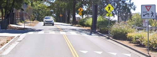
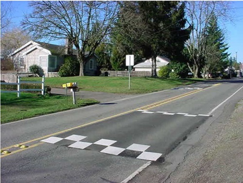
| Speed Table/Raised Crosswalk |
 |
| Description: A speed table is a vertical traffic calming device, similar to a speed hump, that runs transverse to the direction of traffic. Speed tables are longer than speed humps, typically having a ramp up of approximately six feet followed by a 10 feet minimum flat section and a ramp down of six feet. |
| CA MUTCD: Sections 2C.29 | 3B.18 | 3B.25 | 3B.26 | Figure 3B-30 |
| Caltrans DIB: 82-06 | 93 |
| Other Guidance: FHWA Traffic Calming ePrimer (3.12 | 3.14) | ITE Traffic Calming Fact Sheet - Speed Table/Raised Crosswalks | NACTO Urban Street Design Guide - Speed Table |
| Offset Speed Table |
 |
| Description: An offset speed table provides the speed limiting benefits of a speed table, while allowing emergency vehicles to pass through with minimal delay. An offset speed table is a speed table split in half down the street centerline with longitudinal separation between the two halves. |
| CA MUTCD: Sections 2C.29 | 3B.18 | 3B.25 | 3B.26 | Figure 3B-30 |
| Other Guidance: FHWA Traffic Calming ePrimer (3.13) | ITE Traffic Calming Fact Sheet - Speed Tables/Raised Crosswalks | NACTO, ITE Offset Speed Tables for Reduced Emergency Response Delay |
| Transverse Rumble Strips |
 |
| Description: Transverse rumble strips are raised or grooved patterns installed perpendicular to the direction of travel in the roadway travel lane. They provide an audible and tactile warning of a downstream decision point. |
| Standard Plans: Portable Transverse Rumble Strip T13 |
| CA MUTCD: Sections 3J.02 | 6F.87 |
| Other Guidance: FHWA Factors Influencing Operating Speeds and Safety on Rural and Suburban Roads |
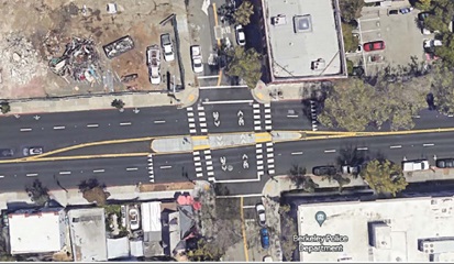
| Raised Intersection |
 |
| Description: A raised intersection is a vertical traffic calming device that raises the entirety of an intersection by three to four inches. The ramp sections of the intersection are approximately six feet in length with no greater than a 5% slope. |
| Caltrans DIB: 82-06 |
| Other Guidance: FHWA Traffic Calming ePrimer (3.15) | ITE Traffic Calming Fact Sheet - Raised Intersection | NACTO Urban Street Design Guide - Raised Intersection |
| PHYSICAL ROADWAY SEGMENT MODIFICATIONS |
| Lateral Shifts |
 |
| Description: A lateral shift is a realignment of an otherwise straight street that causes travel lanes to shift. The primary purpose of a lateral shift is to reduce motor vehicle speed along the street. A typical lateral shift separates opposing traffic through the shift with the aid of a median island. |
| CA MUTCD: Sections 6C.08 |
| Caltrans DIB: 93 |
| Other Guidance: FHWA Traffic Calming ePrimer (3.4) | ITE Traffic Calming Fact Sheet - Lateral Shift |
| Chicanes |
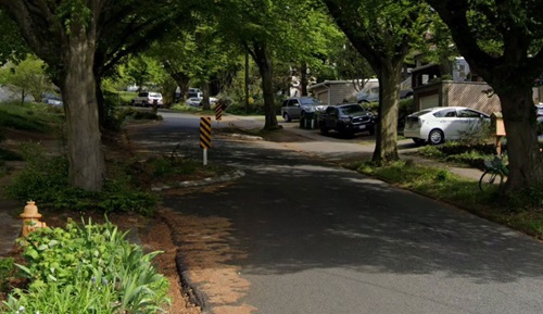 |
| Description: Chicanes are a series of narrowing elements, such as curb extensions, that alternate from one side of the street to the other, forming an S-shaped, curvilinear roadway alignment. They introduce horizontal curvature to the road, breaking up the "runway effect" of wide and straight streets. |
| HDM: Topic 303.4 | 404 |
| Caltrans DIB: 93 |
| Other Guidance: FHWA Traffic Calming ePrimer (3.5) | ITE Traffic Calming Fact Sheet - Chicane |
| OTHERS |
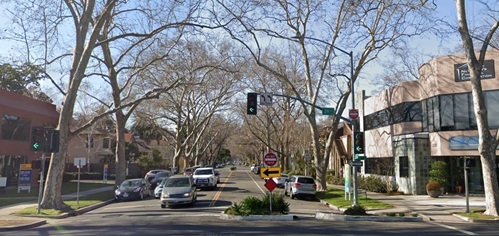
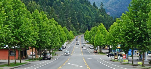
| Street Trees and Landscaping |
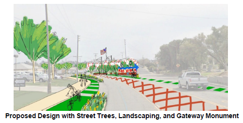 |
| Description: Street trees and landscaping can contribute to a reduction in the rate of crashes. This effect is often attributed to a perceived narrowing of the roadway, a sense of rhythm and human scale created by framing the street, and the perception that the driver is in a place where they are more likely to encounter pedestrians, bicyclists, and cross-traffic. |
| HDM: Indexes 201 | 309 | 405.1 | 901.2 | 904.3 | 904.5 |
| Caltrans DIB: 82-06 |
| Other Guidance: Caltrans Encroachment Permits Manual Section 506 | FHWA Speed Management ePrimer | NCHRP Report 737 - Design Guidance for High=Speed to Low-Speed Transition Zones for Rural Highways |
| In-Roadway Lights |
 |
| Description: In-Roadway Lights (IRWLs) are a special type of highway traffic signal installed in the roadway surface to warn road users that they are approaching a condition on or adjacent to the roadway. |
| CA MUTCD: Chapter 4N |