Appendix E – Water Quality Technical Memorandum
Executive Summary
This Technical Report is being prepared to update and supplement the Water Quality Report (WQR) prepared in 2009 for the I-5 North Coast Corridor (NCC) project. The purpose of this technical report is to provide additional information related to the recently adopted Caltrans NPDES permit and to describe the Department's practices and policies that are implemented by the various divisions to ensure all NPDES Permit mandates are complied with and documented.
The limits and descriptions of the project have not changed since the WQR was completed. A Locally Preferred Alternative (LPA) has been selected and information presented in this technical report centers around the work being conducted in support of the LPA.
Caltrans permit was adopted by the State Water Resources Control Board (currently pending final approval of the Environmental Protection Agency and Office of Administrative Law), and is discussed in this technical report to ensure compliance with latest Permit requirements is identified and referenced during the project development process by the Department's Design Division and other functional units involved with the project development team. Furthermore, the SWRCB adopted a revised Construction General Permit (CGP) in 2009 which Caltrans projects are subject to. Specific CGP mandates not discussed in the 2009 WQR are addressed in this Technical Memorandum.
In 2010, EPA approved the latest CWA Section 303d impaired water listing and scheduling for assignment of TMDL requirements; a revised table is included showing impaired water bodies within the project limits. The Total Maximum Daily Load (TMDL) work that is being addressed by the named dischargers (Caltrans, municipalities and other named stakeholders) is ongoing and Comprehensive Load Reduction Plans (CLRPs) are proposed to comply with Waste Load Allocations and other impairments. This technical report also discusses specific design procedures such as Caltrans infiltration tool calculation, low impact development, hydromodification and other requirements that are being assessed and documented for project implementation.
Design has prepared drainage basin delineation for both existing and preliminary design of the LPA. The current design has emphasized minimizing pavement areas; previous I-5 NCC documents such as the draft environmental document or the 2009 WQR included a larger impervious footprint than the current LPA. This technical memorandum discusses differences between existing and proposed impervious areas as well as existing treatment within the corridor which accounts for approximately 7% for the whole project footprint while after completion of the I-5 NCC, there will be approximately 27% of the treatment of the total combined pavement based on the preliminary design.
I. NPDES Permits
I.1 Caltrans Statewide NPDES Permit
The State Water Resources Control Board adopted Order No. 99-06–DWQ, NPDES No.
CAS000003 NPDES Permit Statewide Storm Water Permit and Waste Discharge Requirements (WDRs) For the State of California, Department Of Transportation (Caltrans) properties, facilities, and activities herein referred to as Permit. The permit requires the Department to implement a Storm Water Management Plan, SWMP; which purpose is to protect and achieve water quality standards at all times. The minimum requirement is to ensure that pollutants in discharges from storm drain systems owned or operated by Caltrans are reduced to the maximum extent practicable (MEP) and that pollutants in discharges from construction activities covered by the General Construction Permit are reduced by employing Best Available Technology /Best Conventional Technology (BAT/BCT) performance standards. The MEP analysis is the process of evaluating the selected BMPs based on legal and institutional constraints, technical feasibility, relative effectiveness, and cost/benefit ratio.
The Department continues to comply with CWA§402 by complying with the requirements of the statewide NPDES permit The permit and the approved SWMP consolidated the Department's stormwater compliance activities under one permit and provided a framework for consistent and effective implementation of stormwater management practices on a statewide basis. This permit has been re-issued (Order 20012-011 DWQ) as of September 2012 and will have an effective date of July 1, 2013.
The Department continues to modify its guidance documents including, but not limited to, the Project Planning and Design Guide, Construction Storm Water Manuals and is currently in process of updating the Department's SWMP in coordination with SWRCB and RWQCBs to reflect latest Caltrans permit requirements.
I.2 Construction General NPDES Permit
The State Water Resources Control Board adopted Order No. 2009-0009–DWQ, NPDES No. CAS000002 NPDES General Permit for Storm Water Discharges Associated with Construction and Land Disturbance Activities on September 2, 2009, with an effective date of July 1, 2010. The permit covers construction activities that result in land disturbance of equal or greater than one acre or construction activities that result in land surface disturbance of less than one acre if the construction activity is part of a common plan of development.
The permit requires the dischargers to implement a Storm Water Pollution Prevention Plan (SWPPP) that contains BMPs that will prevent construction pollutants from entering a receiving water body.
The SWPPP has the following objectives:
- All pollutants and their sources, including sources of sediment-associated with construction, site erosion and other activities associated with construction are controlled;
- Where not otherwise required to be under a Regional Water Board permit, all non-storm water discharges are identified and either eliminated, controlled, or treated;
- Site BMPs are effective and result in the reduction or elimination of pollutants in stormwater discharges and authorized non-storm water discharges from construction activity to the BAT/BCT standard;
- Calculations and design details, as well as BMP controls for site run-on, are complete and correct, and
- Stabilization BMPs installed to reduce or eliminate pollutants after construction.
I.2.1 Risk Level Determination
The new Construction General Permit is a risk-based permit that establishes three levels of environmental risk possible for a construction site. The Risk Level (RL) is calculated in two parts: 1) Project Sediment Risk, and 2) Receiving Water Risk. The RL determination quantifies sediment and receiving water characteristics and uses these results to determine the project's overall RL. Highly erodible soils, in higher rainfall areas, on steep slopes increase the 'sediment risk'. Monitoring and reporting requirements increase as the RL goes from 1 to 3.
The Department's stormwater program complies with the substantive provisions of the Construction General Permit on projects. The permit requirements are implemented during the design phase through water pollution control plans and project specifications. During the construction phase, the requirements will be met through the implementation of the Stormwater Pollution Prevention Plans (SWPPPs) prepared for each project under the construction phase of the project and compliance with the project's specifications.
I.2.2 RUSLE 2
Once the construction phase is complete and the project is stabilized, the Resident Engineer will work with the stormwater group to complete a Notice Of Termination (NOT) and file with the SDRWQCB. This lets the regional board know that the project is no longer subject to CGP requirements but will still be in compliance with the Caltrans NPDES Permit.
One of the means of providing the validation of final soil stabilization is to provide computational proof using the Erosion Prediction Procedure (EPP) developed by Caltrans in 2008. The EPP uses the RUSLE2 computer program to estimate soil erosion loss and sediment transport in natural and disturbed construction sites. The EPP achieves "site stabilization" for a project through the use of simulated temporary and permanent BMPs, allowing the Project Engineer (PE) to assess the effect of the design parameters on soil erosion and sediment transport.
As part of designing the final stabilization of project surfaces, the PE uses RUSLE2 to generate the computation proof that sediment yield and stabilization are equivalent to or better than preconstruction conditions. The information is produced from representative cross-sections of slope surfaces that validate the erosion control design as having equal or better protection than existing conditions (pre-construction). This information is included as part of the project's SWDR.
II. Affected Watershed
Table II.1 below lists the hydrologic areas/subareas that are within the proposed I-5 NCC Project. The table compares the area of each of the hydrologic areas or sub-areas versus the existing Caltrans right of way within the I-5 project limits. The table shows that the maximum Caltrans tributary area to any of the hydrologic subareas is less than two percent.
Table II.1 Existing I-5 Contribution to the watershed within project limits
* Source: sangis/landuse/right_of_way.shp
| Watershed | Hydrologic Area/Sub Area Name | HA/HSA Number | HA/HSA (Acres) | Existing I-5 Tributary Area* (Acres) | Existing I-5 Contribution to HA/HSA (%) |
|---|---|---|---|---|---|
| Peñasquitos | Miramar HA | 906.40 | 25924 | 288 | 1.10% |
| San Dieguito | Miramar Reservoir HA | 906.10 | 32,594.8 | 332 | 1.02% |
|
Carlsbad |
Rancho Santa Fe HSA | 905.11 | 22,610.5 | 221 | 0.98% |
| San Elijo HSA | 904.61 | 20,721.5 | 181 | 0.88% | |
| Batiquitos HSA | 904.51 | 17,819.4 | 330 | 1.85% | |
| Encinas HA | 904.40 | 2,991.4 | 47 | 1.56% | |
| Los Monos HSA |
904.31 |
11,904.4 | 95 | 0.8% | |
| El Salto HSA | 904.21 | 7,476.4 | 134 | 1.79% | |
| Loma Alta HA | 904.10 | 5,199.6 | 40 | 0.78% | |
| San Luis Rey | Mission HSA | 903.11 | 29,930 | 114 | 0.38% |
| Santa Margarita | Lower Ysidora HSA | 902.11 | 6710 | 38 | 0.57% |
II.1 Section 303 (d) of the Clean Water Act and & the Targeted Design Constituent
The CWA requires states to identify and make a list of surface water bodies that do not meet water quality standards, also referred to as "water quality limited segments", even after discharges of wastes from point sources have been treated by the minimum required levels of pollution control technology. States are required to compile these water bodies into a list, referred to as the "Clean Water Act Section 303(d) List of Water Quality Limited Segments" (List).
As part of Caltrans runoff characterization studies, The Department has identified pollutants that are discharging with a load or a concentration that commonly exceeds allowable standards and which are considered treatable by Caltrans approved treatment BMPs. These pollutants are referred to as Targeted Design Constituents (TDCs), which include sediment, metals (total and dissolved zinc, lead and copper), nitrogen, phosphorus, and general metals.
Table II.2 below lists the 303(d) listed water bodies that will be potentially impacted by the proposed I-5 north coast corridor-widening project.
Table II.2 303(d) Impaired Water Bodies within project limits
Source: http://www.waterboards.ca.gov/sandiego/water_issues/programs/303d_list/index.shtml N/A= Not Applicable
| Hydrologic Area | Water Body Name | HA/ HSA | Size | Pollutant | Caltrans TDC |
|---|---|---|---|---|---|
| Peñasquitos | Soledad Canyon | 906.10 | 2 Miles | Selenium, Sediment Toxicity | N/A |
| Los Peñasquitos Creek | 906.10 | 12 Miles | Total Dissolved Solids, Selenium, Toxicity, Total Nitrogen as N, Fecal Coliform, Enterococcus | Sediment, Nitrogen | |
| Los Peñasquitos Lagoon | 906.10 | 469 Miles | Sedimentation/Siltation | Sediment | |
| Rose Creek | 906.4 | 13 Miles | Selenium, Toxicity | N/A | |
| San Dieguito | San Dieguito River | 905.11 | 19 Miles | Total Dissolved Solids, Toxicity, Nitrogen, Fecal Coliform, Enterococcus, Phosphorus | Sediment, Nitrogen Phosphorus |
| Carlsbad | Loma Alta Creek | 904.10 | 8 Miles | Selenium, Toxicity | N/A |
| Buena Vista Creek | 904.21 | 11 Miles | Selenium, Sediment Toxicity | N/A | |
| Buena Vista Lagoon | 904.21 | 202 Miles | Indicator Bacteria, Nutrients, Sedimentation/Siltation | Sediment, Nutrients (N and P) | |
| Agua Hedionda Creek | 904.31 | 7 Miles | Total Dissolved Solids, Selenium, Toxicity, Total Nitrogen as N, Fecal Coliform, Enterococcus, Phosphorus, Manganese | Sediment, Nitrogen Phosphorus | |
| Cottonwood Creek | 904.51 | 2 Miles | Sediment Toxicity, Selenium, DDT | N/A | |
| Encinitas Creek | 904.51 | 3 Miles | Toxicity, Selenium | N/A | |
| San Marcos Creek | 904.51 | 19 Miles | Selenium, Sediment Toxicity, Phosphorus, DDE | Phosphorus | |
| San Elijo Lagoon | 904.61 | 566 Miles | Sedimentation/Siltation, Indicator Bacteria, Eutrophic | Sediment | |
| Escondido Creek | 904.62 | 26 Miles | Total Dissolved Solids, Selenium, Toxicity, Total Nitrogen as N, Fecal Coliform, Enterococcus, DDT Phosphate, Sulfates, Manganese | Sediment, Nitrogen Phosphorus | |
| San Luis Rey | San Luis Rey River, Lower (west of I-15) | 903.11 | 19 Miles | Chloride, Fecal Coliform, Phosphorus, Total Dissolved Solids, Total Nitrogen as N, Toxicity, Enterococcus | Phosphorus, Nitrogen |
| Pacific Ocean Shoreline, at San Luis Rey River mouth | 0 Miles | Enterococcus, Total Coliform | N/A | ||
| Santa Margarita | Oceanside Harbor | 902.11 | 52 Miles | Copper | Copper |
III. Best Management Practices
Best Management Practices (BMPs) are considered to address potential water quality impacts during the planning and design, construction, and operational and maintenance phases. The SWMP divides the BMPs into separate categories from the planning and design phase to the operational and maintenance phase.
Short term potential impacts to water quality during the construction phase are avoided and or minimized through the use of Construction Site BMPs while the long term potential impacts, due to operation and maintenance of the freeway or other Department facilities, are avoided/minimized through the use of Design Pollution Prevention BMPs, Treatment BMPs, and Maintenance BMPs
The general categories of BMPs have been identified for use in the Project Planning and Design Guide (PPDG) Manual and are shown in Table III.1 BMP Descriptions.
Table III.1 BMP Descriptions
Source: PPDG Manual, Table 2-3, July 2010
| BMP | Description |
|---|---|
| Design Pollution Prevention BMPs | Preservation of existing vegetation, concentrated flow conveyance, slope/surface protection, etc. |
| Treatment BMPs | Treatment Devices and facilities. |
| Construction Site BMPs | Temporary soil stabilization and sediment control, non-storm water management, and waste management. Refer to the Construction BMP Manual. |
| Maintenance BMPs | Litter picks up, waste management, street sweeping, etc. |
III.1 Department Standard Procedures and Practices
III.1.1 Project Planning and Design
During the process of planning and design of all new facilities and reconstruction or expansion of existing facilities, the Project Engineer considers and, as appropriate, incorporates BMPs. Design Pollution Prevention BMPs are permanent measures to reduce pollution discharges after construction is completed; while Treatment BMPs are permanent measures to improve/maintain stormwater quality after construction is completed.
Project-specific BMP consideration is an iterative process that begins with initial project planning and scoping activities. As the project moves into detailed design, the Department's design division revisits the BMP consideration process and goes through a detailed BMP selection methodology that works efficiently with the design of the highway and drainage facilities. This process is documented in the Storm Water Data Report.
III.1.2 Storm Water Data Report
Every Caltrans project is required to complete a Storm Water Data Report (SWDR), which summarizes the stormwater decisions made by the Project Development Team. These decisions are made taking into consideration grading, environmental constraints, utility issues and any other conflicts that might arise when designing a project. The SWDR documentation includes various checklists to help project engineers determine the feasibility of BMPs and any potential conflicts related to their implementation. The SWDR is initiated at the beginning of the project and is updated as the project progresses through design. The final SWDR not only documents the decisions made throughout the phases of the project but also includes exhibits showing tributary drainage areas, percentages of treatment, water quality impairments and types of design pollution prevention, construction and maintenance BMPs that will be incorporated into the project.
A PA/ED level SWDR is being prepared for this project and is in the process of being finalized for the initial phase of design. The work done to date includes delineation of impervious surface tributary drainage areas and preliminary siting and selection of potential treatment BMPs.
III.1.3 Design Pollution Prevention (DPP) BMPs
During the project development process, the Project Engineer will incorporate specific DPP BMPs into a project to minimize potential impacts to water quality. The design objectives of the DPP BMPs are as follows:
- Prevent Downstream Erosion.
- Stabilize Disturbed Soil Areas.
- Maximize Vegetated Surfaces Consistent with Existing Caltrans Policies.
The table below lists the DPP BMPs to achieve the above design objectives. The SWDR will include a discussion of applicable DPPs and also document through the completed checklist the process used to determine DPP applicability.
Table III.1.3.1 Design Pollution Prevention BMPs
Source: PPDG Manual, Table 2-4, 2010
| Consideration of Downstream Effects Related to Potentially Increased Flow | |
|---|---|
| Peak Flow Attenuation Basins | Soil Modification |
| Reduction of Paved Surface (i.e., increase the previous area) | Energy Dissipation Devices |
| Preservation of Existing Vegetation | |
| Concentrated Flow Conveyance Systems | |
| Ditches, Berms, Dikes, and Swales | Channel Linings |
| Overside Drains, Downdrains, Paved Spillways | Flared Culvert End Sections |
| Outlet Protection/Velocity Dissipation Devices | |
| Slope/Surface Protection Systems | |
| Vegetated Surfaces | Flared Culvert End Sections |
| Hard Surfaces |
III.1.4 Low Impact Development (LID)
Caltrans encourages the use LID features, which can mutually serve as both Design Pollution Prevention BMPs and Treatment BMPs; Due to limited right of way and the linear nature of the typical Caltrans project, the design must ensure that any design features do not create a safety hazard for the public or maintenance forces. LID uses site design and stormwater management to maintain the site's pre-project runoff rates and volumes by using design techniques that infiltrate, filter, store, evaporate, and detain runoff close to the source.
Features that function as LID measures include, but are not limited to:
- Surface vegetation, such as biofiltration swales and strips;
- Soil amendments, such as compost and surface roughening;
- Subsurface storage, such as dry-wells, infiltration trenches, or swales underlain with permeable soil layers;
- Small detention areas, such as cisterns, traps, and check dams;
- Pervious materials, such as paving stone and porous concrete, when used in lieu of impervious materials at locations outside the highway prism;
- Disconnected drainage that relies upon overland flow rather than pipe networks to convey runoff to discharge locations; and,
- Contour Grading, grading that follows natural flow paths and terrain with an emphasis upon slope rounding and gradual elevation changes.
This project will review and propose LID features throughout the project footprint. Final selection will be made during the final design once drainage, grading, and other design features are determined and used as the basis for feasibility and siting locations.
III.1.5 Hydromodification
The Department under its recently adopted statewide permit (Order 2012-0011-DWQ- effective date of July 1, 2013) is required to conduct a risk-based approach to ensure the project does not cause a decrease in lateral (bank) and vertical (channel bed) stability in receiving stream channels. The Department will assess pre-project channel stability and implementing mitigation measures that are appropriate to protect structures and minimize stream channel bank and bed erosion.
The permit requires that projects that add 1 acre or more of new impervious surface with any impervious portion of the project located within a Threshold Drainage Area (area draining to a location at least 20 channel widths downstream of a stream crossing (a pipe, swale, culvert, or bridge) within Project Limits) must conduct a rapid assessment of stream stability at each stream crossing (e.g., pipe, culvert, swale or bridge) within that Threshold Drainage Area. If the stream crossing is a bridge, a follow up rapid assessment of stream stability is also required.
- If the results of the rapid assessment indicate that the representative reach is laterally and vertically stable (i.e., a rating of excellent or good) the Department does not have to conduct further analyses and must implement the Design Pollution Prevention and Treatment BMPs.
- If the results of the rapid assessment indicate that the representative reach will not be laterally and vertically stable (i.e., a rating of excellent or good), the Department must determine whether the instability, in conjunction with the proposed project, poses a risk to existing or proposed highway structures by conducting appropriate Level 2 (and, if necessary, Level 3) analyses.
- If the results of the Level 2 and 3 analysis indicate that the instability, in conjunction with the proposed project, poses a risk to existing or proposed highway structures, other options must be implemented, including, but not limited to, in-stream and floodplain enhancement/restoration, fish barrier removal as identified in the report required under Article 3.5 of the Streets and Highways Code, regional flow control, off-site BMPs, and, if necessary, project re-design.
The project engineer will work with the hydraulics unit and other design support units such as geotechnical to conduct and document the assessment. This evaluation will be included as part of the SWDR at the PSE phase.
III.1.6 Treatment BMPs
Approved Treatment BMPs must be considered for this project as required under the SWMP to avoid or minimize the potential long term impacts from any Department facilities or activities. The approved treatment BMPs listed below are considered to be technically and fiscally feasible. Department experience has found these BMPs to be constructible, maintainable, and effective at removing pollutants to the maximum extent practicable.
The designer will follow Appendix E and the T-checklists found in the PPDG to select and determine specific treatment BMP feasibility. This assessment can be crudely described as
- Determine if there are any TMDL adopted within project limits
- Determine if there are any 303d listed water bodies within project limits
- Determine whether constituents on 303dlist are Department's TDCs
- Evaluate the feasibility of incorporation by ensuring siting criteria is met
- Run WQV/F calculations
- Look at checklist T-1 Part 1
- Run Infiltration Tool
- Complete checklist T-1 part 1-10 thereby completing design criteria evaluation of all Approved Treatment BMPs
- Document in SWDR
Table III.1.6.1 Approved Treatment BMPs
Source: PPDG Manual, Table 2-5, July 2010
| Biofiltration Systems | Infiltration Devices |
|---|---|
| Detention Devices | Traction Sand Traps |
| Dry Weather Flow Diversion | Gross Solid Removal Devices (GSRDs) |
| Media Filters | Multi-Chamber Treatment Train |
| Wet Basins |
A preliminary review of the project area has been completed and potential locations and types of treatment BMPs have been assessed for feasibility (based on criteria outlined in the PPDG and discussed above along with other factors such as climate, water volume, soil conditions, physical limitations, other environmental considerations, etc.). As the proposed project proceeds further into the design phase, the locations of these treatment BMPs would be further evaluated to determine feasibility in relation to right-of-way limitations, environmental constraints, and hydraulic capacity. In addition, in areas where treatment BMPs cannot be incorporated due to the above-mentioned reasons, vegetation will be maximized and every effort will be made to ensure the successful establishment of landscaping and erosion control throughout the project limits. The project will also consider any future treatment BMPs that might be approved by Caltrans from the ongoing research and monitoring program.
Description, design criteria and siting consideration of approved treatment BMPs are presented below. The SWDR will document decisions made by the PE to determine the feasibility and implementation of treatment BMPs to deal with TDCs and other parameters as required by the Permit and outlined in the PPDG.
III.1.6.1 Biofiltration Strips and Swales
Biofiltration Strips are vegetated land areas, over which stormwater flows as sheet flow. Biofiltration Swales are vegetated channels, typically configured as trapezoidal or v-shaped channels that receive and convey stormwater flows while meeting water quality criteria and other flow criteria.
Pollutants are removed by filtration through the vegetation, sedimentation, adsorption to soil particles, and infiltration through the soil. Strips and swales are effective at trapping litter, Total Suspended Solids (soil particles), and particulate metals. In most cases, flow attenuation is also provided, thus biofiltration swales and strips can also be considered a LID technique. Caltrans Biofiltration Swale Design Guidance and Caltrans Biofiltration Strips Design Guidance for complete guidance on design criteria, site evaluation, and preliminary and final design.
Description
Biofiltration Strips are sloped vegetated land areas located adjacent to impervious areas, over which stormwater runoff flows as sheet flow. Pollutants are removed by filtration through the vegetation, uptake by plant biomass, sedimentation, adsorption to soil particles, and infiltration through the soil. Biofiltration Swales are vegetated, typically trapezoidal channels, which receive and convey stormwater flows while meeting water quality criteria and other flow criteria. Pollutants are removed by filtration through the vegetation, uptake by plant biomass, sedimentation, adsorption to soil particles, and infiltration through the soil.
When properly implemented, biofiltration strips and swales are aesthetically pleasing. Due to the presence of its vegetation, the public views these devices as a "landscaped roadside" this would make placement more acceptable than other Treatment BMPs using concrete vaults.
Appropriate Applications and Siting Criteria
Biofiltration Strips and Swales should be considered wherever site conditions and climate allow vegetation to be established and where flow velocities will not cause scour. A minimum vegetative cover of approximately 70% is required for treatment to occur. Biofiltration Strips and swales are one of several BMPs for the treatment of stormwater runoff from project areas that are anticipated to produce pollutants of concern (e.g., roadways, parking lots, maintenance facilities, etc.).
III.1.6.2 Infiltration Devices
An Infiltration Device is designed to remove pollutants from surface discharges by capturing the Water Quality Volume (WQV) and infiltrating it directly to the soil rather than discharging it to surface waters. Infiltration devices may be configured as basins or trenches.
The following sections give a brief overview of infiltration devices and a summary of design criteria.
Description
Infiltration Basins are a volume-based Treatment BMP that temporarily store runoff in bermed or excavated areas for later infiltration over a limited period. During a storm, runoff enters the Infiltration Basin during which time the water level in the basin rises. During the rainfall, and for some time after it ends, the runoff infiltrates into the soil through the invert area, which is sized depending upon the design volume of runoff to be treated, the permeability of the soil below the invert, and the period selected for infiltration (between 24 to 96 hours, but typical projects use 40 to 48 hours). Overflow events (when the runoff during rainfall events rises above the WQV elevation) are released, typically through a spillway through the confining berm or an overflow riser.
Infiltration Basins should be considered wherever site conditions allow and the design WQV exceeds 0.1 acre-feet.
An Infiltration Trench utilizes relatively shallow excavations backfilled with gravel or other high porosity materials to create subsurface storage for runoff that will over a design period infiltrate into the surrounding soils. Infiltration Trenches are often elongated, allowing them to be used in constricted areas, but there is no shape restriction.
The WQV should be directed to the Infiltration Trench by gravity flow in an open channel or as sheet flow and the captured volume should flow downward within the trench by the action of gravity and without vertical piping for distribution to lower depths of the trench.
Since infiltration trenches can be sited in circuitous alignments and sometimes implemented within a disconnected and distributed pattern, the BMP can also be considered a LID technique. Infiltration Devices are considered the most effective Treatment BMP against most pollutants. Due to the effectiveness of treatment, Infiltration Devices are always the first choice to be considered when selecting a Treatment BMP for a Caltrans project.
Appropriate Applications and Siting Criteria
Infiltration Devices should be considered wherever site conditions allow. Appropriate sites for Infiltration Devices should have:
- a) Sufficient soil permeability;
- b) A sufficiently low water table;
- c) The influent would not present a threat to local groundwater quality; and
- d) Sufficient elevation to allow gravity drainage of the device when needed for maintenance purposes (Infiltration Basin only).
III.1.6.3 Detention Devices
A Detention Device is a permanent treatment BMP designed to reduce the sediment and particulate loading in runoff from the water quality design storm (Water Quality Volume [WQV]). While the WQV is temporarily detained in the device sediment and particulates settle out under the quiescent conditions prior to the runoff being discharged. A Detention Device is typically configured as a basin.
Detention Basins can remove litter, settable solids, total suspended solids, particulate metals, and absorbed pollutants such as heavy metals, oil, and grease by capturing, temporarily detaining, and gradually releasing stormwater runoff.
The following sections give a brief overview of detention devices and a summary of design criteria. The PE shall refer to Caltrans Detention Basins Design Guidance for complete guidance on design criteria, site evaluation, and preliminary and final design.
Description
Detention Basins operate by intercepting runoff and detaining it long enough for the sediment and particulates to settle out under quiescent conditions prior to the runoff being discharged. Detention Basins are typically designed to completely drain after a storm event and are normally dry between rain events. Detention Basins are designed for water quality purposes but they must also operate safely and effectively as part of the overall highway drainage system. Detention Basins must safely pass the peak drainage facility design event in accordance with the HDM.
In addition, Detention Basins should be able to operate by gravity flow while limiting clogging of the water quality outlet and providing a proper overflow spillway or overflow riser for larger runoff volumes. The basins should only require occasional maintenance and cleaning. Entering flows should be distributed uniformly at low velocity to prevent re-suspension of settled materials and to encourage quiescent conditions. Low flow channels are often used to ensure conveyance to the outlet and to limit erosion during low flows. Basin shape and/or configuration should result in as natural an appearance as possible.
Appropriate Applications and Siting Criteria
Detention Devices and other approved Treatment BMPs should be considered for implementation wherever Infiltration Devices are not feasible. For Detention Devices, the WQV should be at least 0.1 acre-foot and site conditions must meet criteria.
Sufficient hydraulic head should be available so that water stored in the device does not cause an objectionable backwater condition in the upstream storm drain system. The seasonally high groundwater should be at least 10 ft below the invert of the Basin unless a liner is used.
III.1.6.4 Dry Weather Flow Diversion
Dry Weather Flow Diversion (DWFD) devices provide permanent treatment by directing non-stormwater flow through a pipe or channel to a local municipal sanitary sewer system during the dry season or dry weather. This flow must be generated by Caltrans activities or facilities.
Description
Typically, dry weather flow diversions consist of a berm or wall constructed across the dry weather flow drainage channel so the dry weather flows are diverted to a pipe or channel leading to the sanitary sewer. A gate, weir, or valve should be installed to stop the diversion during the wet season or storms during the wet season. Accordingly, the conveyance to the sanitary sewer should be sized for the dry weather flows only. Wet weather flow is diverted back to the stormwater conveyance system.
If possible, a screen or trash rack should be installed at the diversion to reduce the likelihood of clogging the diversion pipe or channel. Maintenance vehicle access should be provided, especially if a screen is installed.
Appropriate Applications and Siting Criteria
DWFD should only be considered when all of the following conditions apply:
- Dry weather flow is persistent, and contains pollutants;
- An opportunity for connecting to a sanitary sewer is reasonably close and would not involve extraordinary plumbing, features or construction practices to implement;The POTW is willing to accept the flow during the dry season or dry weather.
III.1.6.5 Media Filters
A Media Filter Treatment BMP device primarily removes TSS pollutants (sediments and metals) from runoff by sedimentation and filtering, and also is effective for dissolved metals, litter and potentially some nutrients (depending upon the type of Media Filter selected).
Description
There are two types of approved Media Filter devices: The Austin Sand Filter and the Delaware Sand Filter; each is configured using two chambers. An Austin Sand Filter is usually open and at grade and has no permanent water pool; a Delaware Sand Filter is always configured with closed chambers and below grade and has a permanent pool of water. An Austin Sand Filter may be configured with earthen or concrete sides and invert; a Delaware Sand Filter is always made using concrete sides and invert.
In both types of Media Filters, stormwater is directed into the first chamber where the larger sediments and particulates settle out, and the partially treated effluent is metered into the second chamber to be filtered through a media. In the Austin Sand Filter, the first chamber may be sized for the entire WQV ('full sedimentation') or as a 'partial sedimentation' chamber, holding only about 20% of the WQV; the Delaware Sand Filter holds the entire WQV in the initial chamber and is designed to pass the WQV from the second chamber.
The treated effluent (filtered water) is captured by perforated underdrains for release downstream. There is a drop in elevation of 3 ft to 6 ft between the invert of the inlet pipe and the invert of the device outflow pipe depending on device type, size or configuration.
The filter media typically consists of sand, which is effective for the removal of coarse and fine sediments and particulate metals. Other materials, such as topsoil or organic materials may be added to the sand to increase the treatment capacity for some pollutants (for example, dissolved metals) but these additives often increase the nitrogen and phosphorus concentration levels in the effluent. When media filters are used to encourage infiltration or subsurface storage and mimic natural hydrology within small applications, then the media filters may be considered a LID technique.
Appropriate Applications and Siting Criteria
The minimum WQV for Media Filters is ≥ 4,356 ft3 (0.1 acre-ft [a-f]) Sites proposed for Media Filters must have sufficient hydraulic head to operate by gravity; generally between 3 to 6 ft of elevation drop is needed between the inflow to the initial chamber and effluent outflow from the second chamber.
Media Filters will perform better if the tributary area has a relatively high percentage of impervious area, and low sediment loading.
Standard details for a vector-proof Delaware Sand Filter have been developed when vector control is an issue.
For earthen-type Media Filters, at least 10 ft separation from seasonally high groundwater should be provided. For vault-type Media Filters, the level of the concrete base of the vault must be above seasonally high groundwater unless by special design.
III.1.6.6 Wet Basin
Wet Basins are detention systems comprised of a permanent pool of water, a temporary storage volume above the permanent pool, and a shoreline zone planted with aquatic vegetation. Wet Basins are designed to remove pollutants from surface discharges by temporarily capturing and detaining the Water Quality Volume (WQV) in order to allow settling and biological uptake to occur. Wet Basins are recommended for the following pollutants: Total Suspended Solids (TSS); nutrients; particulate metals; pathogens; litter; and Biological Oxygen Demand (BOD).
Description
A Wet Basin has temporary storage capacity above the permanent pool for the Water Quality Volume. The WQV enters the Wet Basin and commingles with the permanent pool, during which time the water level in the basin rises to inundate the surrounding vegetation during a WQ event. The commingled water is slowly discharged through a water quality riser until the water level returns to the level of the permanent pool.
The level of the permanent pool must be maintained year-round to support the plant community in the Wet Basin; this water level is maintained by connecting the Wet Basin to a stream channel, by seepage from springs, or by water from some other source.
Appropriate Applications and Siting Criteria
The site under consideration for a Wet Basin should, if possible, be located where the visual aesthetics of the permanent pool is considered a benefit (such as a roadside rest area or vista point). The proposed site must have a source of water to provide base flow sufficient to maintain a year-round plant community to account for losses due to infiltration and evapotranspiration. The soil immediately below the invert must be relatively impermeable to limit the loss of water by infiltration (NRCS Hydrologic Soils Group [HSG] soils C and D) unless a liner is used. The separation between seasonally high groundwater and basin invert should be > 10 ft; use liner if separation is between 1.0 ft and 10 ft unless approved by the local RWQCB due to the presence of low permeability soils [Hydrologic Soil Groups C or D]).
Conditions that do not allow for siting are: sites having contaminated soils or groundwater plumes; objectionable backwater conditions in the storm drain system are induced; placement on or near unstable slopes, or slopes steeper than 15 percent.
Note also that if the impounded volume exceeds 15 a-f then the Wet Basin may classify as a jurisdictional dam and be subject to other requirements; consult with District Hydraulics if the volume below the spillway exceeds this threshold.
Specific information about Multi-Chamber Treatment Train, Gross Solids Removal devices and Traction Sand Traps are not included since the project location, TDC or operations do not meet the design criteria.
III.1.7 Water Quality Volume/ Flow
Water Quality Volume (WQV)
Treatment BMPs are designed to treat the lower volume or flow of more frequent (i.e. return period < 1 year) storm events. The volume associated with the frequent events are commonly referred to as the WQV for BMPs designed based on volume, and Water Quality Flow (WQF) for BMPs designed based on flow.
Treatment BMPs are sized to accommodate the WQF or WQV from the contributing drainage area. Flows in excess of these values are diverted around or through the Treatment BMP. Methods for determining the WQV are generally tied to an analysis of rainfall depths generated over 24-hour periods although the WQV may be determined by the drawdown time of certain Treatment BMPs.
The WQV of Treatment BMPs is based on using either of the following methods:
- Where they are established, sizing criteria from the RWQCB or local agency (whichever is more stringent) will be used; or
- Where the RWQCB or local agency does not have an established sizing criterion, Caltrans will use the following method:
Water Quality Flow (WQF)
The listed values of rainfall intensity are used in the Rational Formula (Q=CiA) to estimate runoff from areas that would discharge flow to flow-based Treatment BMPs. The resulting runoff rate would be the design WQF to be used at any specific site. The WQF is the primary design criteria used for various types of flow-based Treatment BMPs (e.g. Biofiltration Swales). Caltrans, the SWRCB and the nine RWQCBs worked cooperatively to establish these values. For San Diego, the negotiated rainfall intensity is 0.20"/hr region-wide. In addition to designing for the WQF, the PE must also ensure that the flow-based Treatment BMPs include a bypass or an overflow device to convey peak discharges from larger design storms consistent with Section 861.3 of the Highway Design Manual.
III.1.8 Infiltration Tool
In order to determine infiltration by vegetated and earthen BMPs, the Department created a workbook containing two separate tools: the Strip and Swale Infiltration Tool (SSIT) and the Basin Infiltration Tool (BIT). The SSIT was created to estimate infiltration for biofiltration strips and swales, infiltration trenches, and other subsurface infiltration practices.
The BIT was created to estimate infiltration for infiltration basins and detention basins. The values generated by these tools are intended to be used in the SWDR, which requires the input of an infiltration estimate for four scenarios:
- flow across native soil or existing fill,
- flow across amended soil, 3) infiltration basins, and 4) detention basins.
The output generated will be used by Design to determine whether infiltration is occurring and whether it can be increased by the use of compost or other soil amendments.
III.1.9 Existing Treatment BMPs within the I-5 Corridor
Litigation between the Department and the Natural Resource Defense Council (NRDC), Coast Keepers and the United States Environmental Protection Agency (USEPA) resulted in a requirement to develop a Best Management Practice (BMP) Retrofit Pilot Program in District 7 and 11 (BMP Retrofit Pilot Program). Moreover, subsequent to the Statewide Permit adoption (Order 99-06-DWQ), and as described in SWMP section 4.4.1 and PPDG, Caltrans conducts an assessment whenever new construction or reconstruction is taking place, documented in the SWDR. Below is a list of the treatment BMPs that have been constructed within the I-5 corridor as either part of the BMP Retrofit Pilot Program or ongoing construction projects along with some photographs.
Table III.1.9.1 Existing Treatment BMPs within the I-5 North Coast Project*
Source: BMP Retrofit program Final Report (CTSW-RT-01-050) and project files (EAs 0301U4, 06510,2358U4). *Park and Ride treatment numbers not included in table.
| Watershed | Location Description | BMP type | Total Tributary Area (Treated Acres) |
|---|---|---|---|
| Peñasquitos | N Roselle St, 5/805 I-5/SR-56 | Biofiltration Swales Detention Basin | 7.7 |
| San Dieguito |
|
Biofiltration Swales and Detention Basin Biofiltration Swales | 24 |
| Carlsbad |
|
Biofiltration Swales Detention Basin Wet Basin Biofiltration Swale | 15 |
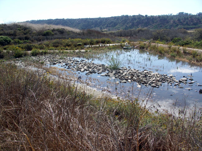
I-5/SR-56 Detention Basin after a storm event.
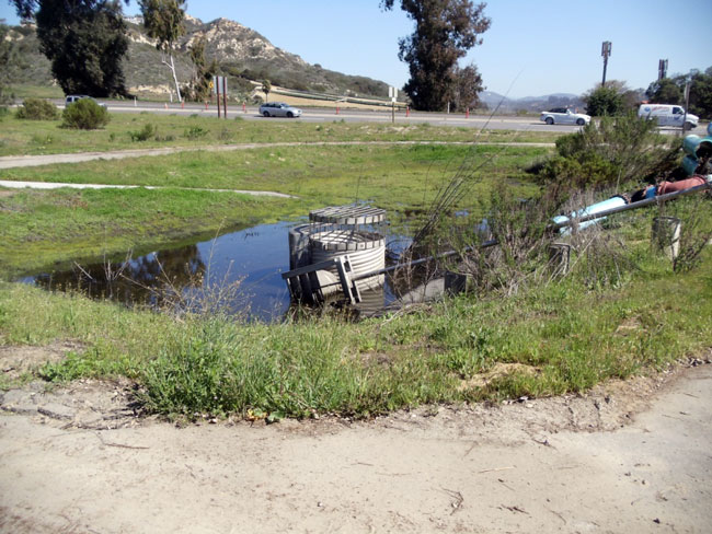
I-5 at Manchester Ave. Detention Basin after a storm event.
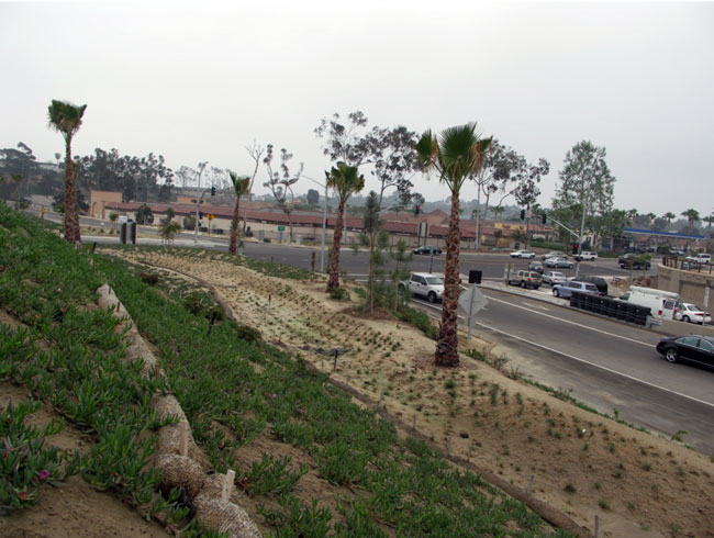
I-5 @ Lomas Santa Fe Biofiltration Swales after construction.
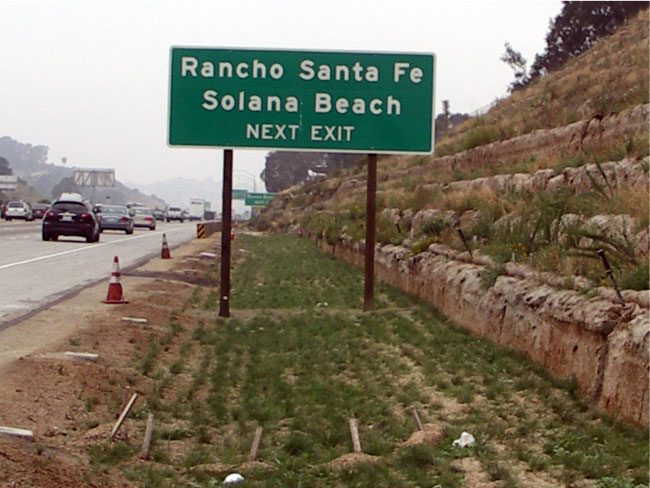
I-5 @ Lomas Santa Fe Biofiltration Swales after construction (Solana Beach sign).
III.1.10 Current Pavement Areas
Table III.1.10.1 below shows existing and proposed pavement acreage by watershed for the I-5 NCC project. These calculations differ from previously provided numbers as a result of more precise cross-section and design information; previous data was based on GIS data.
Table III.1.10.1 Pavement Acreage
Total Existing Impervious Area: 669.2 Acres. Total Proposed Impervious Area: 214.5 acres.
| Watershed/ Hydrologic Area | Sub watershed/ Major Water Bodies | Location | Existing Impervious Area (Acres) | Proposed Impervious Area (Acres) | ||
|---|---|---|---|---|---|---|
| Peñasquitos 906 | Rose Canyon | La Jolla V. Dr. To Voight St | 11.7 | 193.5 | 8.7 | 30.0 |
|
Peñasquitos |
Voight St To Roselle St | 33.1 | 15.0 | |||
| 5/805 To SR 56 | 115.1 | 0.0 | ||||
| SR 56 – Del Mar Height Ave | 33.6 | 6.3 | ||||
| San Dieguito 905 |
San Dieguito |
Del Mar - S. Dieguito River | 38.5 | 90.2 | 12.7 | 29.0 |
| S. Dieguito - V.V. Blvd | 14.2 | 9.4 | ||||
| V. V. - Lomas Santa Fe Ave | 37.5 | 6.9 | ||||
| Carlsbad 904 | San Elijo Lagoon | Loma. - Manchester Ave | 14.5 | 327.8 | 20.2 | 142.3 |
| Man. - Birmingham Ave | 38.3 | 19.0 | ||||
| Cottonwood | Bir. - Encinitas Blvd | 28.3 | 12.7 | |||
| Enc - Leucadia Ave | 15.1 | 6.8 | ||||
| Batiquitos | Leu - La Costa Ave | 36.6 | 12.6 | |||
| L.C. - Poinsettia Lane | 19.1 | 8.3 | ||||
| Encinas | Point - Palomar Air. Rd | 27.3 | 10.7 | |||
| Pal - Cannon Rd | 32.9 | 11.3 | ||||
| Agua Hedionda Lagoon | Cannon - Tamarack Ave | 16.7 | 7.2 | |||
| Tamarack -Carlsbad V. Dr | 28.2 | 9.0 | ||||
| Buena Vista Lagoon | Carlsbad - SR 78 | 21.9 | 7.2 | |||
| SR 78 - Cassidy St | 21.0 | 4.4 | ||||
| Loma Alta Creek | Cass. - Oceanside Blvd | 10.1 | 5.4 | |||
| O.Blvd. - Mission Ave | 17.8 | 7.5 | ||||
| San Luis Rey 903 | San Luis Rey | Mission - SR 76 | 16.8 | 46.0 | 4.5 | 12.4 |
| SR 76 - Harbor Dr | 29.2 | 7.9 | ||||
| Santa Margarita 902 | Santa Margarita (Oceanside Harbor) | Harbor - Vandergrift Blvd | 11.7 | 11.7 | 0.8 | 0.8 |
III.1.11 Proposed Treatment BMPs
As discussed above, there has been preliminary siting for treatment BMPs based on the current footprint. Based on the proposed areas that will receive treatment, an equivalent of 112 % of the new pavement will receive treatment.
Table III.1.11.1 Treatment Acreage for I-5 NCC Project
Total Existing Treatment Acreage: 46.9 Total Proposed Treated Acreage: 240.5
| Watershed/ Hydrologic Area | Sub watershed/ Major Water Bodies | Location | Existing Treatment Acreage | Proposed Treated Acreage | ||
|---|---|---|---|---|---|---|
| Peñasquitos 906 | Rose Canyon | La Jolla V. Dr. To Voight St | 0.0 | 7.8 | 9.8 | 41.7 |
|
Peñasquitos |
Voight St To Roselle St | 0.9 | 25.1 | |||
| 5/805 To SR 56 | 6.9 | 6.9 | ||||
| SR 56 – Del Mar Height Ave | 0.0 | 0.0 | ||||
| San Dieguito 905 |
San Dieguito |
Del Mar - S. Dieguito River | 17.7 | 24.1 | 23.2 | 36.4 |
| S. Dieguito - V.V. Blvd | 0.0 | 4.3 | ||||
| V. V. - Lomas Santa Fe Ave | 6.4 | 9.0 | ||||
| Carlsbad 904 | San Elijo Lagoon | Loma. - Manchester Ave | 2.0 | 15.0 | 3.1 | 137.8 |
| Man. - Birmingham Ave | 4.8 | 18.1 | ||||
| Cottonwood | Bir. - Encinitas Blvd | 0.0 | 25.7 | |||
| Enc - Leucadia Ave | 0.0 | 11.5 | ||||
| Batiquitos | Leu - La Costa Ave | 4.1 | 24.9 | |||
| L.C. - Poinsettia Lane | 0.0 | 10.3 | ||||
| Encinas | Point - Palomar Air. Rd | 0.0 | 8.2 | |||
| Pal - Cannon Rd | 0.0 | 9.3 | ||||
| Agua Hedionda Lagoon | Cannon - Tamarack Ave | 0.0 | 0.0 | |||
| Tamarack -Carlsbad V. Dr | 0.0 | 0.0 | ||||
| Buena Vista Lagoon | Carlsbad - SR 78 | 0.0 | 0.0 | |||
| SR 78 - Cassidy St | 0.0 | 11.3 | ||||
| Loma Alta Creek | Cass. - Oceanside Blvd | 0.0 | 0.0 | |||
| O.Blvd. - Mission Ave | 0.0 | 15.5 | ||||
| San Luis Rey 903 | San Luis Rey | Mission - SR 76 | 0.0 | 0 | 6.1 | 19.5 |
| SR 76 - Harbor Dr | 0.0 | 13.4 | ||||
| Santa Margarita 902 | Santa Margarita (Oceanside Harbor) | Harbor - Vandergrift Blvd | 0.0 | 0 | 5.0 | |
Summary Table of I-5 NCC Impervious Areas being treated
Proposed Equivalent Area Treated (proposed treated/added impervious): 112%
| Existing | Proposed (includes existing) | |
|---|---|---|
| Impervious | 669.2 acres | 883.57 acres |
| Treated Impervious | 46.9 acres | 240.5 acres |
| % Treatment | 7% | 27% |
IV. Project Operation And Maintenance
The Division of Maintenance performs various activities on different facilities throughout the state to ensure safe and usable conditions for the public. Most of the activities are performed by small crews with minimal soil disturbance.
IV.1 Maintenance of Treatment BMPs
The operation and maintenance requirements for each type of treatment BMPs are outlined in Family F-7 and Appendix C of the maintenance staff guide, they are included in the following pages.
C.23 Structural Treatment System Maintenance
Revised October 2007
The following systems represent the approved structural treatment best management practices (STBMPs) that have been approved as technically and fiscally feasible in reducing constituents of concern to improve water quality. The systems include:
- Biofiltration Strips and Swales (Section C.23.1),
- Infiltration Basins (Section C.23.2),
- Infiltration Trenches (Section C.23.3),
- Detention Devices (Section C.23.4),
- Traction Sand Traps (Section C.23.5),
- Gross Solids Removal Devices (Section C.23.6),
- Austin Sand Filters (Section C.23.7),
- Delaware Sand Filters (Section C.23.8),
- Multi-Chambered Treatment Trains (Section C.23.9), and
- Wet Basins (Section C.23.10).
This section of the Staff Guide describes typical STBMPs and their recommended maintenance.
Actual field STBMPs may vary from the standard schematics shown in this section. The division of Maintenance supervisory staff may modify the recommended frequency of maintenance activity on a site-specific basis to ensure functionality.
The previous study of STBMPs demonstrated that inspection frequency and vegetation management were primary cost factors (BMP Retrofit Pilot Study Final Report, CTSW-RT-01-050). Consequently, these items are minimized in these guidelines, though other district policies, such as fire safety and aesthetics, may dictate more frequent maintenance. Further, with increasing numbers of STBMPs, it is critical that the maximum amount of necessary work is accomplished with each site visit. To this end, it is recommended that STBMP inspectors carry the necessary equipment (Table C-61) to unclog a BMP that needs immediate maintenance. If the BMP is inspected 3 days after a storm event, concurrent unclogging may allow draining before the 96hour limit for vector breeding and vector control district consultation. It also allows subsequent maintenance, if needed, to be scheduled during a dry period rather than the period immediately following a storm, which is often a period of peak demand on maintenance resources.
There may be occasions where emergencies arise, such as accidents, toxic spills, or other incidents, where immediate response is needed. On those occurrences, Caltrans crews will respond to the emergency, on a priority basis and, if necessary, the BMP will be taken out of service until the BMP functionality can be restored. The goal for such critical situations is to have the BMP back into service within 30 days.
Prior to intrusive maintenance at any BMP, maintenance personnel should check with the District biologist to ensure there are no endangered species, threatened species or species of special concern within the BMP maintenance area.
This section does not include maintenance that may be necessary for vector control of devices that hold a permanent pool of water where vector prevention has failed. In such cases, the local vector control authority should be consulted.
For many treatment BMPs, the wet season inspections are scheduled 3 days after substantial rainfall events (0.75 inches is suggested for most areas of California), which requires tracking storm size and when the storm event ended. A rain gauge at the maintenance station can be used to verify storm size. There are also Internet resources, such as weather.com where the 'yesterday' tab gives precipitation measurements.
Table C-61. Inspection and Unclogging Equipment list
| Item | Purpose |
|---|---|
| Hard hat, boots, gloves | Safety and comfort |
| Camera, inspection forms, tape measure | Documentation |
| Plumbing snake and thin rod | Unclogging orifices |
| Metal rake | Breaking up accumulated sediment that acts as dams, scarifying infiltration basins and filters |
C.23.1 Biofiltration Strips and Swales
Revised October 2008
Description:
These measures are intended to maintain established biofiltration swales and strips as effective devices for treating runoff discharges. These requirements for inspection and maintenance will allow the devices to continue to function as designed for water quality purposes.
Appropriate Application:
The BMP maintenance described in Table C-62 and Table C-63 apply to personnel that inspects and maintain biofilter swales, where water depths tend to be deeper than strips so plant height guidelines may be helpful to performance. For strips, the Roadside Vegetated Treatment Sites (RVTS) Study (CTSW-RT-07-127.01.2) characterized the treatment benefit of roadside strips that did not have a water quality based maintenance program. The comparison of the RVTS results with previous studies suggests that maintenance of biofiltration strips, beyond the Department's current statewide protocols for vegetation, does not enhance pollutant removal. Therefore, biofiltration strips and other RVTS-type areas that receive sheet flow should be maintained according to existing district maintenance protocols. Further, some areas may have strips that do not have vegetation to design standards (e.g. 80 percent coverage) because soil and climate may limit the success of the establishment. In these cases, stormwater treatment benefits may still occur, mostly from infiltration, so a continual effort to force the establishment of vegetation may not be justified. Refer to the District landscape architect office for advice on identifying these circumstances.
Swales tend to have higher water depths than strips, so preventative and corrective maintenance for maintaining plant vegetation height should be implemented.
The preventative maintenance routine is described in Table C-62, and the corrective maintenance activities are described in Table C-63.
Chemical vegetative control measures will not be used on vegetated treatment BMPs except where Caltrans is directed by the California Department of Food and Agriculture to treat the BMPs for invasive weeds. Fire control strips up to 2.4 meters (8 feet) wide may be maintained through pesticide applications adjacent to biofiltration swales. The areas used for fire control will not be considered as part of the treatment system. Report the use of chemicals in the Caltrans Stormwater Management Annual Report.
Implementation:
Field measurements of maintenance indicators are made by visual observation. Frequencies provided are for the minimum required level of service. Greater maintenance frequencies may be required depending on the particular site and level of traffic. A schematic of a biofiltration swale and strip is shown in Figure C-10.
Table C-62: Biofiltration Swales Systems Preventative Maintenance
| Frequency | Routine Action | Activity Cut-Sheet |
|---|---|---|
| Annually | Mow grass, grass-lined swales, and strips to an average height of 6 inches | B-40 |
Table C-63: Biofiltration Swales Maintenance Activities
| Maintenance Indicator | Inspection Frequency | Maintenance Activity |
|---|---|---|
| Evidence of significant channeling, erosion, seeps, or ponding. | Annually in the late wet season. | Correct channelized, eroded, seeped, or ponded areas using additional fill and vegetation depending on coverage and/or by removing accumulated sediment. Complete prior to the next wet season. |
| Average vegetation height exceeds 12 inches, emergence of trees, or woody vegetation. | Semi-Annually, once during the wet season, once during the dry season (depending on growth). | Cut vegetation to an average height of 6 inches; cuttings may be removed at the discretion of District Maintenance. |
| Less than 80 percent coverage in swale invert and swale side slope. | Semi-Annually, once late wet season and once late dry season. | Assess the quantity needed and reseed/revegetate barren spots by November. Contact environmental or landscape architect for appropriate seed mix. Scarify area to be restored, to a depth of 2-inches. Restore side slope coverage with a hydroseed mixture. If growth is unsuccessful after 2 applications (2 seasons) of reseeding/revegetating, an erosion blanket or equivalent protection should be installed over eroding areas. |
| Debris/trash present. | Inspect during routine trash collection. | Remove litter and debris per routine District schedule. |
| Sediment at or near vegetation height, channeling of flow within swale and energy dissipaters, inhibited flow due to change in slope. | Annually in the dry season. |
|
| Burrows, holes, mounds. | Annually and after vegetation trimming. | Where burrows cause erosion or jeopardize structural integrity, backfill firmly. |
| Water accumulation in spreader ditch and/or collector ditch for more than 72 hours. | Within 72 hours after a storm event 0.75 inches or greater. If no such event occurs before April 1, conduct wet season inspections in April. | At the time of inspection, de-water the spreader ditch to a depth of less than 0.25 inches. If sediment impedes the de-watering activity, then move or remove that portion of the sediment. Dispose sediment properly. |
| Inlet structures, outlet structures, side slopes or other features hindered by debris or damaged, significant erosion, fence damage, graffiti, vandalism, etc. | Semi-Annually, late wet and late dry season. | Repair/take corrective action prior to wet season. Contact the District Maintenance Storm Water Coordinator if repairs /solutions are not readily available in the field. The District Maintenance Storm Water Coordinator will coordinate with appropriate staff for repairs/solutions. |
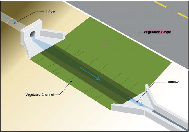
Figure C-10 - Schematic of a Biofiltration Swale & Strip.
C.23.2 Infiltration Basins
Revised October 2009
Description:
These measures are intended to maintain infiltration basins as effective devices for treating runoff discharges. These requirements for inspection and maintenance will allow the devices to continue to function as designed for water quality purposes.
Appropriate Applications:
The BMP maintenance described in Table C-64 and Table C-65 apply to personnel who inspect and maintain infiltration basins. The preventative maintenance routine is described in Table C-64, and the actual maintenance activities are described in Table C65. A schematic of an infiltration basin is shown in Figure C-11.
Implementation:
Field measurements of maintenance indicators are made by visual observation. The illustration below provides a graphical representation of the drain time threshold for standing water:
Table C-64 Infiltration Basin Preventative Maintenance
| Frequency | Routine Action | Activity Cut-Sheet |
|---|---|---|
| Annually at the end of the wet season | Trim vegetation to an average height of 6 inches. | B-39, B-40 |
Table C-65: Infiltration Basin Maintenance Activities
| Maintenance Indicator | Inspection Frequency | Maintenance Activity |
|---|---|---|
| The emergence of trees or woody vegetation | Once during the wet season, once during the dry season. | Remove any trees, or woody vegetation at District Maintenance discretion, reasons may include maintenance access, clogged inlets, or tree preservation requirements in the coastal zone. |
| Debris/trash present | Inspect during routine trash collection- Minimum twice per year. | Remove and dispose of trash and debris per routine District schedule. |
| Standing water for more than 72 hours | Annually 3 days after a 0. 75-inch storm event. If no such event occurs before April 1, conduct wet season inspections in April. |
|
| Standing water for more than 96 hours | 1 day after the above inspection where standing water was observed and action taken. | Notify the District Maintenance Storm Water Coordinator/Vector Control District. |
| Sediment depth exceeds marker on staff gage | Annually in the dry season. |
|
| Evidence of erosion | During dry season. |
|
| Burrows, holes, mounds | Annually and after vegetation trimming. | Where burrows cause erosion or jeopardize structural integrity, backfill firmly. |
| Inlet structures, outlet structures, side slopes or other features hindered by debris or damaged, significant erosion, graffiti or vandalism, fence damage, etc. | Semi-Annually, the late wet season and late dry season. | Take corrective action prior to the wet season. If repair solutions are not readily available in the field notify the District Maintenance Storm Water Coordinator who will coordinate with appropriate staff. |
| Average plant height is greater than 12 inches | Inspect once during the wet season and once during the dry season. | Cut or remove vegetation and clippings as appropriate. |
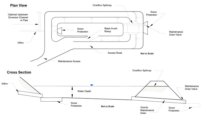
Figure C-11 - Schematic of an Infiltration Basin.
C.23.3 Infiltration Trenches
Revised October 2009
Description:
These measures are intended to maintain effective infiltration trenches for treating runoff discharges. These requirements for inspection and maintenance will allow the devices to continue to function as designed for water quality purposes.
Appropriate Application:
The BMP maintenance described in Table C-66 applies to personnel who inspect and maintain infiltration trenches. The maintenance activities are described in Table C-66. A schematic of an infiltration trench is shown in Figure C-12.
Implementation:
Field measurements of maintenance indicators are made by visual observation. The illustration below provides a graphical representation of the drain time threshold for standing water:
Table C-66: Infiltration Trench Maintenance Activities
| Maintenance Indicator | Inspection Frequency | Maintenance Activity |
|---|---|---|
| Standing surface water for more than 72 hours | Once annually, within 72 hours after a 0.75-inch storm event. If no such event occurs before April 1, conduct wet season inspections in April. |
|
| Standing water for more than 96 hours | 1 day after the above inspection where standing water was observed and action taken. | Notify the District Maintenance Storm Water Coordinator/Vector Control District. |
| Trash/debris present | Inspect during routine trash collection-Minimum twice per year. | Remove and dispose of trash and debris per routine District schedule. |
| Visible sediment | Annually in the dry season. | Remove the top 18-inch layer of the trench, including surface gravel layer, filter fabric, and trench filler material; wash trench filler material and reinstall surface gravel layer, filter fiber, and trench filler material into trench prior to the wet season. |
| Inlet structures, outlet structures, filter fabric or other features hindered by debris or damaged, the emergence of trees or woody vegetation, graffiti or vandalism, fence damage, etc. | Semi-Annually, the late wet season and late dry season. | Take corrective action, prior to the wet season. If repair solutions are not readily available in the field notify the District Maintenance Storm Water Coordinator who will coordinate with appropriate staff. |
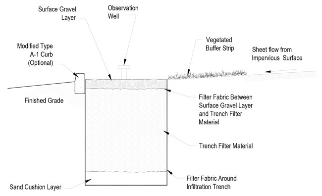
Figure C-12 - Schematic of an Infiltration Trench.
C.23.4 Detention Devices
Revised October 2009
Description:
These measures are intended to maintain effective detention devices for treating runoff discharges. These requirements for inspection and maintenance will allow the devices to continue to function as designed for water quality purposes.
Appropriate Application:
The BMP maintenance described in Table C-67 and Table C-68 apply to personnel who inspect and maintain detention devices. The preventative maintenance routine is described in Table C-67, and the actual maintenance activities are described in Table C68. A schematic of a detention device is shown in Figure C-13. A schematic of a water quality outlet structure is shown in Figure C-14.
Implementation:
Field measurements of maintenance indicators are made by visual observation. The figure below provides a graphical representation of the drain time threshold for standing water:
Table C-67: Detention Device Preventative Maintenance
| Frequency | Routine Action | Activity Cut-Sheet |
|---|---|---|
| Annually at the end of the wet season | Remove accumulated debris around outlet structure. | B-39, B-40 |
Table C-68: Detention Device Maintenance Activities
| Maintenance Indicator | Inspection Frequency | Maintenance Activity |
|---|---|---|
| The emergence of trees or woody vegetation | Once during the wet season, once during the dry season. | Remove any trees, or woody vegetation if interferes with the function of detention basins (impaired access to inlet/outlets, clogged outlets, or reduced storage volume). |
| Trash/debris present | Inspect during routine trash collection. | Remove and dispose of trash and debris per routine District schedule. |
| Evidence of erosion | During dry season. | Reseed/revegetate barren spots prior to the wet season. Contact environmental or landscape architect for appropriate seed mix. Scarify the surface if needed. If after two applications (2 seasons) of reseeding/revegetating and growth is unsuccessful both times, an erosion blanket or equivalent protection will be installed over eroding areas. No erosion blanket will be installed in the basin invert. |
| Standing water for more than 72 hours | Within 72 hours after a storm event 0.75 inches or greater. If no such event occurs before April 1, conduct wet season inspections in April. |
|
| Standing water for more than 96 hours | 1 day after the above inspection where standing water was observed and action taken. | Notify the District Maintenance Storm Water Coordinator/Vector Control District. |
| Sediment depth exceeds marker on staff gage (average 18 inches) | Annually in the dry season. | Remove and properly dispose of sediment. Regrade if necessary. |
| Burrows, holes, mounds | Annually and after vegetation trimming. | Where burrows cause erosion or jeopardize structural integrity, backfill firmly. |
| Inlet structures, outlet structures, side slopes or other features hindered by debris or damaged, significant erosion, graffiti or vandalism, fence damage, etc. | Semi-Annually, the late wet season and late dry season. | Take corrective action prior to the wet season. Consult engineer or District Maintenance Storm Water Coordinator if an immediate solution is not evident. |
| Average plant height is greater than 12 inches | Inspect once during the wet season and once during the dry season. | Cut or remove vegetation and clippings as appropriate. |
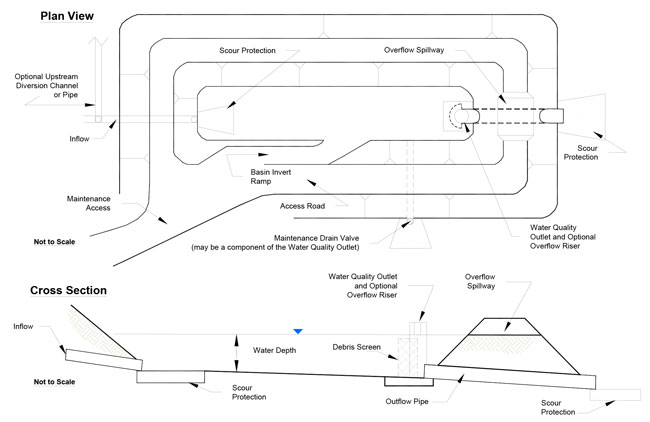
Figure C-13 - Schematic of a Detention Device.
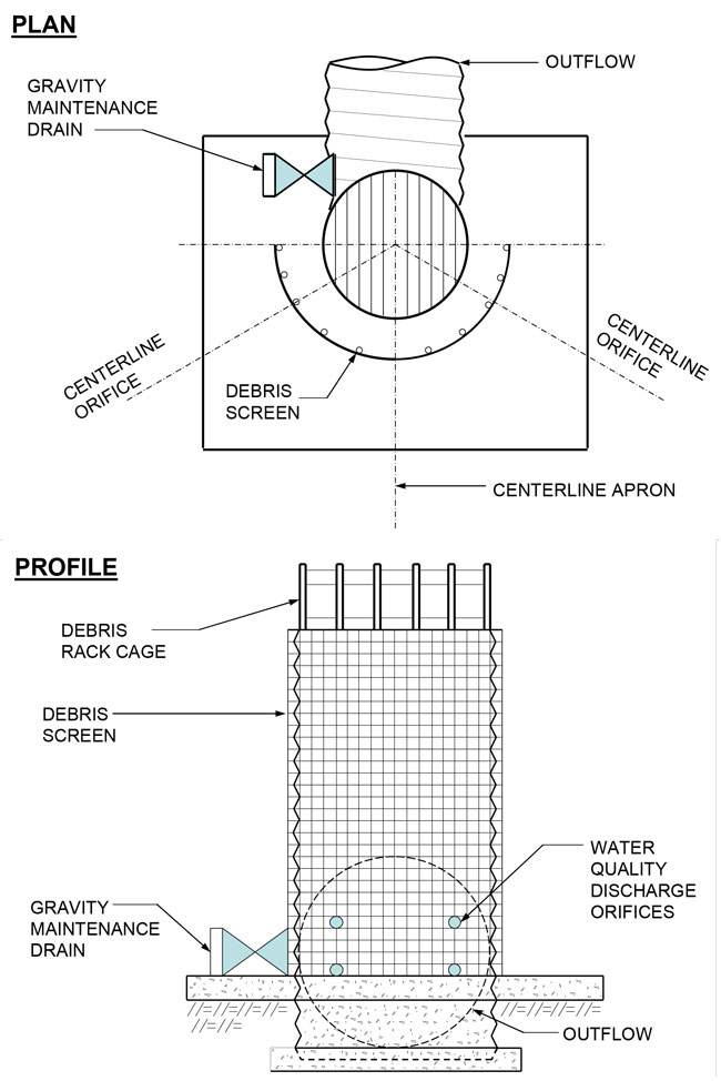
Figure C-14 - Schematic of a Water Quality Outlet Structure.
C.23.5 Traction Sand Trap Devices
Revised October 2009
Description:
This BMP is intended to maintain sand trap devices as effective devices for treating runoff discharges. These requirements for regular inspection and maintenance will allow the devices to continue to function as designed.
Appropriate Applications:
The BMP maintenance described in Table C-69 applies to personnel who inspect and maintain traction sand trap devices. The maintenance activities are described in Table C69.
Implementation:
Field measurements of maintenance indicators are made by visual observation. The illustration below provides a graphical representation of the drain time threshold for standing water. Schematics of a Traction Sand Trap are shown in Figures C-15 and C-16.
Table C-69: Traction Sand Trap Device Maintenance Activities
| Maintenance Indicator | Inspection Frequency | Maintenance Activity |
|---|---|---|
| Sediment volume exceeds the design capacity | Inspect annually and after significant storms |
|
| General maintenance items: Inlet/outlet structural integrity, damaged structures, graffiti or vandalism, etc. | Semi-Annually, the late wet season and late dry season | Take corrective action prior to the wet season. Report general maintenance problems to the District Maintenance Storm Water Coordinator if an immediate solution is not evident. |
| Standing water in the structure, between April 16th and September 30th, 96 hours after a storm event. | Inspect 96 hours after one run- off generating storm per year | Drain facility if possible. If standing water cannot be removed notify the District Maintenance Storm Water Coordinator/Vector Control District. |
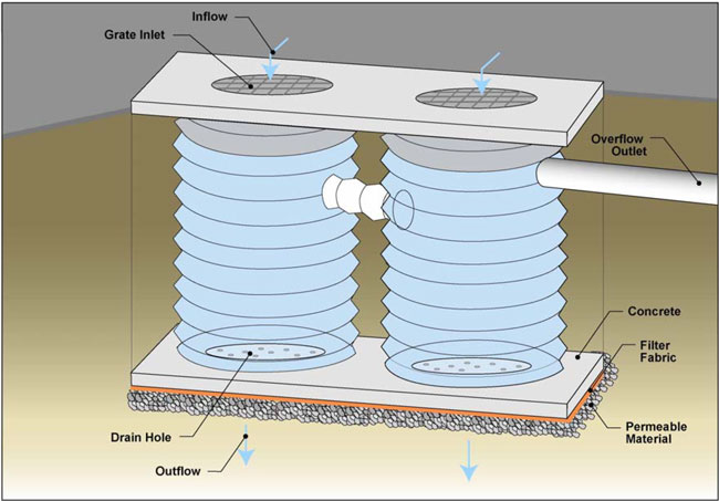
Figure C-15 - Schematic of a Traction Sand Trap (Pipe Inlet Type).
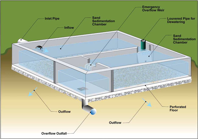
Figure C-16 - Schematic of a Traction Sand Trap (Vault Type).
C.23.6 Gross Solids Removal Devices
Revised October 2009
Description:
This BMP is intended to maintain gross solids removal devices as effective devices for treating runoff discharges. These requirements for regular inspection and maintenance will allow the devices to continue to function as designed.
Appropriate Applications:
The BMP maintenance described in Table C-70 applies to personnel who inspect and maintain gross solids removal devices. The maintenance activities are described in Table C-70. Schematics of a Linear Radial Device are shown in Figures C-17 and C-18. A schematic of Type 1 Inclined Screen Device is shown in Figure C-19, and a schematic of the Type 2 Inclined Screen Device is shown in Figure C-20.
Implementation:
Field measurements of maintenance indicators are made by visual observation. The illustration below provides a graphical representation of the drain time threshold for standing water:
Table C-70: Gross Solids Removal Device Maintenance Activities
1 Monitoring and abatement of vectors may be done through an agreement with the local vector control authority.
| Maintenance Indicator | Inspection Frequency | Maintenance Activity |
|---|---|---|
| Inlet structures, outlet structures, or other features hindered by debris or damaged. Check for graffiti or vandalism. | Semi-Annual Inspection, late dry season and end of the wet season. | Take corrective action prior to the wet season. Report to District Maintenance Storm Water Coordinator if an immediate solution is not evident. |
| Presence of gross solids (trash and debris). | Recommend monthly during the wet season. |
|
| Standing water in structure 72 hours after any storm. | With Semi-Annual Inspection and 72 hours after any storm. | Remove standing water and material that may be impeding complete gravity drainage. |
| Standing water for more than 96 hours | 1 day after the above inspection where standing water was observed and action taken. | Notify the District Maintenance Storm Water Coordinator/Vector Control District. |
|
Screens
|
Minimum Semi-Annually, late dry season and end of the wet season. |
Clean screens. Contact the District Maintenance Storm Water Coordinator if repairs /solutions are not readily available in the field. The District Maintenance Storm Water Coordinator will coordinate with appropriate staff for repairs/solutions. |
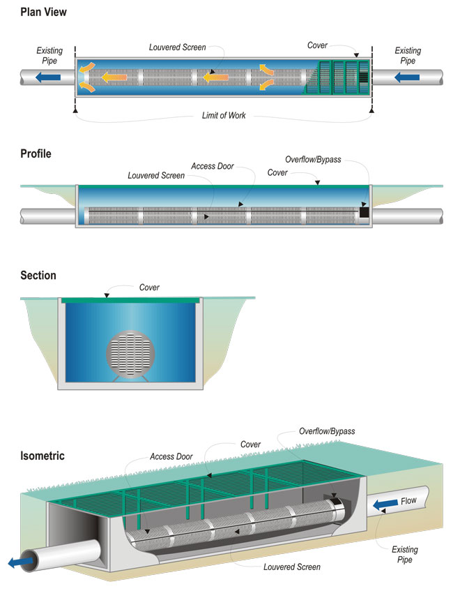
Figure C-17 - Schematic of a Linear Radial Device.
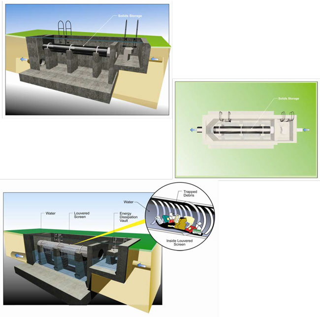
Figure C-18 - Schematic of a Linear Radial Device (HV).
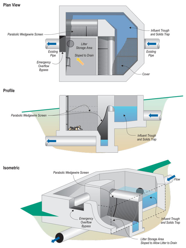
Figure C-19 - Schematic of Type 1 Inclined Screen Device.
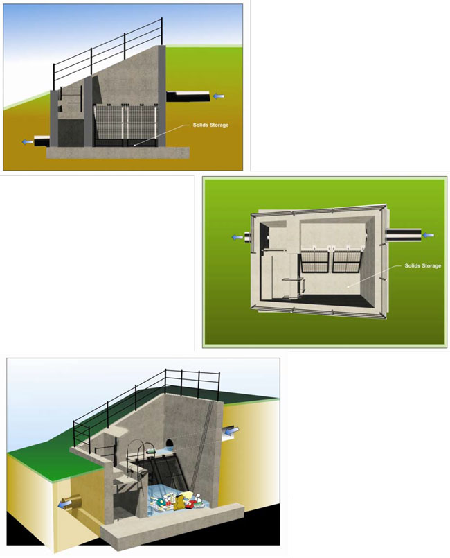
Figure C-20 - Schematic of Type 2 Inclined Screen Device.
C.23.7 Austin Sand Filters
Revised October 2009
Description:
This BMP is intended to maintain Austin sand filters as effective devices for treating runoff discharges. These requirements for regular inspection and maintenance will allow the devices to continue to function as designed.
Appropriate Applications:
The BMP maintenance described in Table C-71 applies to personnel who inspect and maintain Austin sand filters. The maintenance activities are described in Table C-71. A schematic of an Austin Sand Filter is shown in Figure C-21.
Implementation:
Field measurements of maintenance indicators are made by visual observation. The figure below provides a graphical representation of the drain time threshold for standing water:
Table C-71: Austin Sand Filter Maintenance Activities
1 Specification data to replace the sand at the Austin and Delaware media filters and the Multi-Chambered Treatment Trains (MCTTs) can be found within the Caltrans Standard Specifications, May 2006 manual in sections 90-2.02 and 90-3.03. The filter fabric specification for the MCTTs can be found in Caltrans Standard Specifications, May 2006 manual in section 88-1.03 for underdrains. In addition, an apparent opening size of 100 (U.S. Sieve) is recommended. See Appendix D.
| Maintenance Indicator | Inspection Frequency | Maintenance Activity |
|---|---|---|
| Drain time exceeds 72 hours |
Annually, 3 days after a 0.75-inch storm event. If no such event occurs before April 1, conduct wet season inspections in April. |
|
| Standing water for more than 96 hours | 1 day after above inspection where standing water was observed and action taken. | Notify the District Maintenance Storm Water Coordinator/Vector Control District. |
| Sediment depth exceeds marker on staff gage in sedimentation basin; or sediment interferes with gravity drainage in standpipe and/or orifice plate | Annually during dry season. | Remove sediment prior to wet season and dispose of properly. |
| Trash/debris present | Supervisors may set a schedule for debris and trash removal. Minimum is twice per year. | Remove and dispose of trash and debris per routine District schedule. |
| Burrows, holes, mounds | Annual inspections after vegetation trimming. | Where burrows cause erosion or jeopardize structural integrity, backfill firmly. |
| Water accumulation in any structure or other location within the filter | Annually 3 days after a 0.75-inch storm event. If no such event occurs before April 1, conduct wet season inspections in April. |
|
| Inlet structures, outlet structures, filter fabric or other features hindered by debris are damaged or reveal emergence of vegetation, graffiti or vandalism, fence damage, etc. | Semi-Annually, late wet season and late dry season. | Take corrective action for repairs and cleaning. Contact the District Maintenance Storm Water Coordinator if repairs /solutions are not readily available in the field. The District Maintenance Storm Water Coordinator will coordinate with appropriate staff for repairs/solutions. |
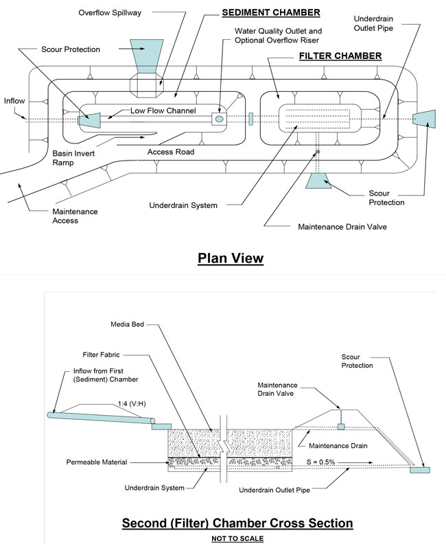
Figure C-21 - Schematic of an Austin Sand Filter. Plan View and Second (Filter) Chamber Cross Section (Not to scale).
C.23.8 Delaware Sand Filters
Revised October 2009
Description:
This BMP is intended to maintain Delaware sand filters as effective devices for treating runoff discharges. These requirements for regular inspection and maintenance will allow the devices to continue to function as designed.
Appropriate Applications:
The BMP maintenance described in Table C-72 applies to personnel who inspect and maintain Delaware sand filters. The maintenance activities are described in Table C-72. A schematic of a Delaware Sand Filter is shown in Figure C-22.
Implementation:
Field measurements of maintenance indicators are made by visual observation. The illustration below provides a graphical representation of the drain time threshold for standing water:
Table C-72: Delaware Sand Filter Maintenance Activities
1 Escondido sand filter restores media to a depth of 12 inches. 2 Specification data to replace the sand at the Austin and Delaware media filters and the Multi-Chambered Treatment Trains (MCTTs) can be found within the Caltrans Standard Specifications, May 2006 manual in sections 90-2.02 and 90-3.03. The filter fabric specification for the MCTTs can be found in Caltrans Standard Specifications, May 2006 manual in section 88-1.03 for underdrains. In addition, an apparent opening size of 100 (U.S. Sieve) is recommended. See Appendix D.
| Maintenance Indicator | Inspection Frequency | Maintenance Activity |
|---|---|---|
| Drain time exceeds 72 hours in the filter chamber | Annually, 3 days after a 0.75-inch storm event. If no such event occurs before April 1, conduct wet season inspections in April. |
|
| Sediment depth exceeds marker on staff gage in the sedimentation basin | Annually during the dry season | Remove sediment prior to the wet season and properly dispose of. |
| Trash/debris present | Supervisors may set a schedule for debris and trash removal. The Minimum is twice per year. | Remove and dispose of trash and debris per routine District schedule. |
| Inlet structures, outlet structures, filter fabric or other features hindered by debris are damaged or reveal the emergence of vegetation, graffiti or vandalism, fence damage, etc. | Semi-Annually, the late wet season and late dry season. | Take corrective action for repairs and cleaning. Contact the District Maintenance Storm Water Coordinator if repairs /solutions are not readily available in the field. The District Maintenance Storm Water Coordinator will coordinate with appropriate staff for repairs/solutions. |
| Valve Leakage | Semi-Annually, the late wet season and late dry season. | Tighten with wrench. |
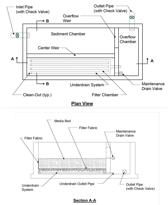
Figure C-22 - Schematic of a Delaware Sand Filter.
C.23.9 Multi-Chambered Treatment Train (MCTT)
Revised October 2009
Description:
This BMP is intended to maintain MCTTs as effective devices for treating runoff discharges. These requirements for regular inspection and maintenance will allow the devices to continue to function as designed.
Appropriate Applications:
The BMP maintenance described in Table C-73 and Table C-74 apply to personnel who inspect and maintain MCTT devices. The preventative maintenance routine is described in Table C-73, and the actual maintenance activities are described in Table C-74. A schematic of a Multi-Chambered Treatment Train is shown in Figure C-23.
Implementation:
Field measurements of maintenance indicators are made by visual observation. The illustration below provides a graphical representation of the drain time threshold for standing water:
Table C-73 Multi-Chambered Treatment Train (Mctt) Preventative Maintenance
| Frequency | Routine Action | Activity Cut-Sheet |
|---|---|---|
| Annually, in Summer |
Replace sorbent pillows in main settling chamber. |
B-48 |
Table C-74: Multi-Chambered Treatment Train (Mctt) Maintenance Activities
1 Specification data to replace the sand at the Austin and Delaware media filters and the Multi-Chambered Treatment Trains (MCTTs) can be found within the Caltrans Standard Specifications, May 2006 manual in sections 90-2.02 and 90-3.03. The filter fabric specification for the MCTTs can be found in Caltrans Standard Specifications, May 2006 manual in section 88-1.03 for underdrains. In addition, an apparent opening size of 100 (U.S. Sieve) is recommended. See Appendix D. 2 At the time of publication, all Caltrans MCTTs have covers that prevent mosquito access to permanent standing water features
| Maintenance Indicator | Inspection Frequency | Maintenance Activity |
|---|---|---|
| Drain time through the filter chamber is greater than 72 hours or sediment accumulation is greater than 0.1 inches over more than 50 percent of the fabric surface area | Annually, 3 days after a 0.75-inch storm event. If no such event occurs before April 1, conduct wet season inspections in April. |
|
| Standing water for more than 96 hours | 1 day after the above inspection where standing water was observed and action taken. | Notify the District Maintenance Storm Water Coordinator/Vector Control District. |
| Trash and debris present | Semi-Annually, the late wet season and late dry season | Remove and dispose of trash and debris. |
| Sediment accumulates to 50% of the volume underneath the tube settlers (~6 inches). Maximum of 2-feet in the grit chamber | Remove tube settler in sedimentation basin and plastic grate in grit chamber; measure sediment depth annually during the dry season | Remove sediment prior to the wet season and properly dispose of. |
| Water accumulation greater than 72 hours in any structure or other location within the device that is not protected from mosquito access 2 | Annually, 3 days after a 0.75-inch storm event. If no such event occurs before April 1, conduct wet season inspections in April. | Take action to drain standing water, such as removing accumulated sediment. |
| Water accumulation greater than 96 hours in any structure or other location within the device that is not protected from mosquito access | 1 day after the above inspection where standing water was observed and action taken. | Notify the District Maintenance Storm Water Coordinator/Vector Control District. |
| Operation greater than 9 years | Every 9 years. | Remove and replace filter media and dispose of properly.1 |
| Sorbent pillows in main settling chamber darkened by oily material | Annually, in Summer. | Annually, renew sorbent pillows, or immediately if pillows are darkened by oily material; and properly dispose of. |
|
Pump –storm status Indicator lights show Amber.
|
Within 72 hours after every storm. | Assess to determine if the problem is electrical or mechanical. Take appropriate action. Replace the pump if needed. |
| Pump-Warranty status | Annually in the dry season. | Inspect pumps for serviceability and required periodic maintenance per manufacturer's guidelines. |
| Inlet structures, outlet structures, pump status indicator lights, filter fabric, settling tubes, mosquito screen over sump pumps (if any), or other features hindered by debris or damaged, the emergence of vegetation, graffiti or vandalism, fence damage, etc. | Semi-Annually, during the wet season and late dry season. | Take corrective action prior to the wet season. Contact the District Maintenance Storm Water Coordinator if repairs /solutions are not readily available in the field. The District Maintenance Storm Water Coordinator will coordinate with appropriate staff for repairs/solutions. |
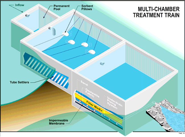
Figure C-23 - Schematic of a Multi-Chambered Treatment Train (MCTT).
C.23.10 Wet Basin
Revised October 2009
Description:
This BMP is intended to maintain wet basins as effective devices for treating runoff discharges. These requirements for regular inspection and maintenance will allow the devices to continue to function as designed.
Appropriate Applications:
The BMP maintenance described in Table C-75 and Table C-76 apply to personnel who inspect and maintain wet basin devices. The preventative maintenance routine is described in Table C-75, and the actual maintenance activities are described in Table C76. A schematic of a wet basin is shown in Figure C-24.
Implementation:
Field measurements of maintenance indicators are made by visual observation. The illustration below provides a graphical representation of the drain time threshold for standing water:
Table C-75: Wet Basin Preventative Maintenance
| Frequency | Routine Action | Activity Cut-Sheet |
|---|---|---|
| Annually prior to the dry season |
Maintain vegetated access road to reduce fire hazard from contact with vehicle catalytic converters. |
B-39, B-40 |
Table C-76: Wet Basin Maintenance Activities
| Maintenance Indicator | Inspection Frequency | Maintenance Activity |
|---|---|---|
| Drawdown greater than 25 hours or water is flowing over the weir | Once during the wet season and after completion or modification of the facility. Inspect 25+ hours after a 0.75-inch storm event. |
If the drawdown is greater than 25 hours:
If water is spilling over weir, open canal gate until the water level is at permanent pool elevation. Check/clear outlet of debris. |
| Burrows, holes, mounds | Annually and after vegetation trimming. | Where burrows cause erosion or jeopardize structural integrity, backfill firmly. |
| Inlet structures, outlet structures, side slopes or other features hindered by debris or damaged, significant erosion, graffiti or vandalism, fence damage, etc. | Semi-Annually, the late wet season and late dry season. | Take corrective action, or restore to as constructed condition prior to the wet season. Contact the District Maintenance Storm Water Coordinator if repairs /solutions are not readily available in the field. The District Maintenance Storm Water Coordinator will coordinate with appropriate staff for repairs/solutions. |
| Observable vegetation coverage/density | Annually. |
|
| Vegetation density is such that mosquito fish cannot swim freely in the planted area | Annually, or at a special request of the local vector control agency. |
|
| Sediment is more than 2 inches in the forebay and 4 inches in the main pond or sediment depth exceeds marker on staff gage | When the pond is drained for Zone 1 vegetation removal or every 3 years. |
|
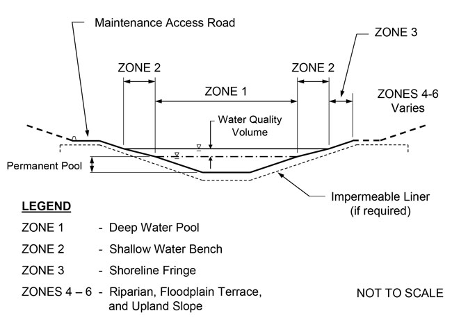
Figure C-24 - Schematic of a Wet Basin.

