This appendix contains the following supporting documentation on visual resources in the North Coast
Corridor (NCC):
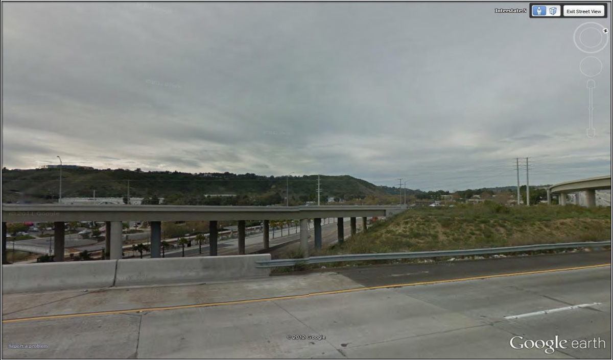
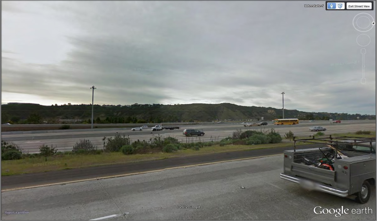
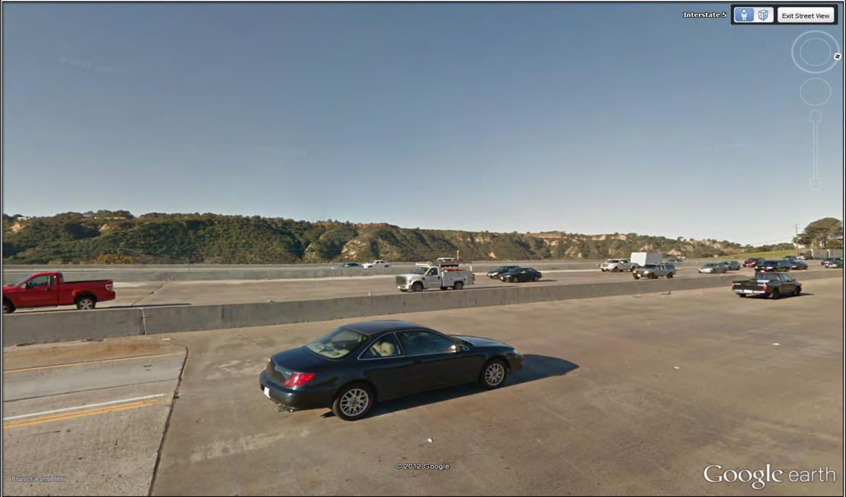
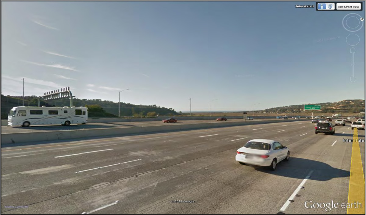
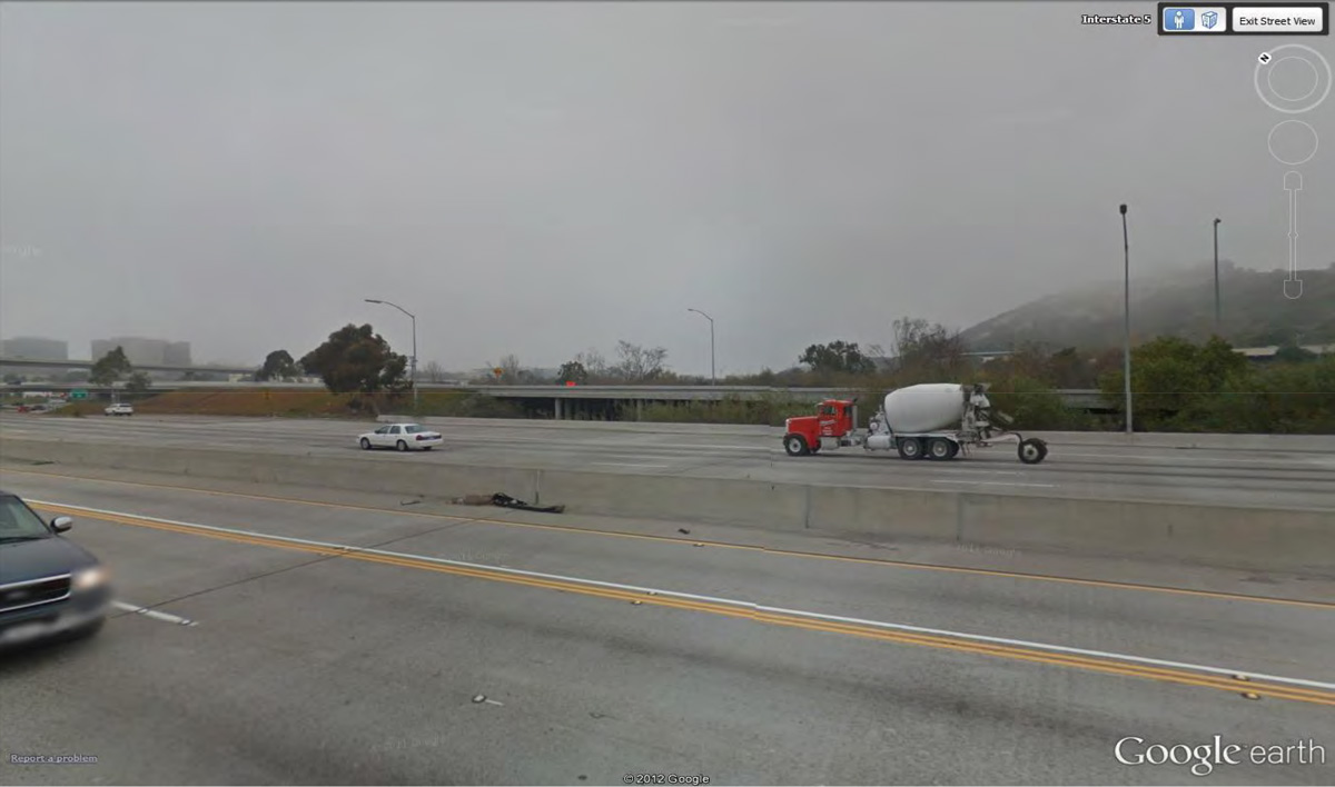
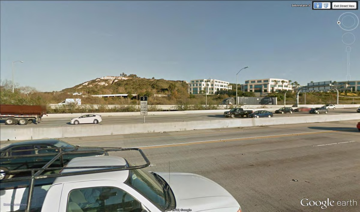
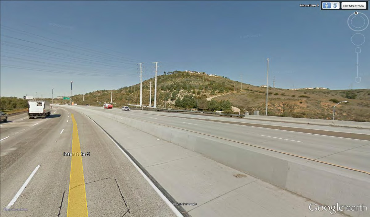
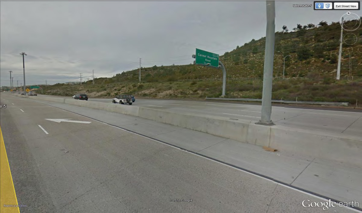
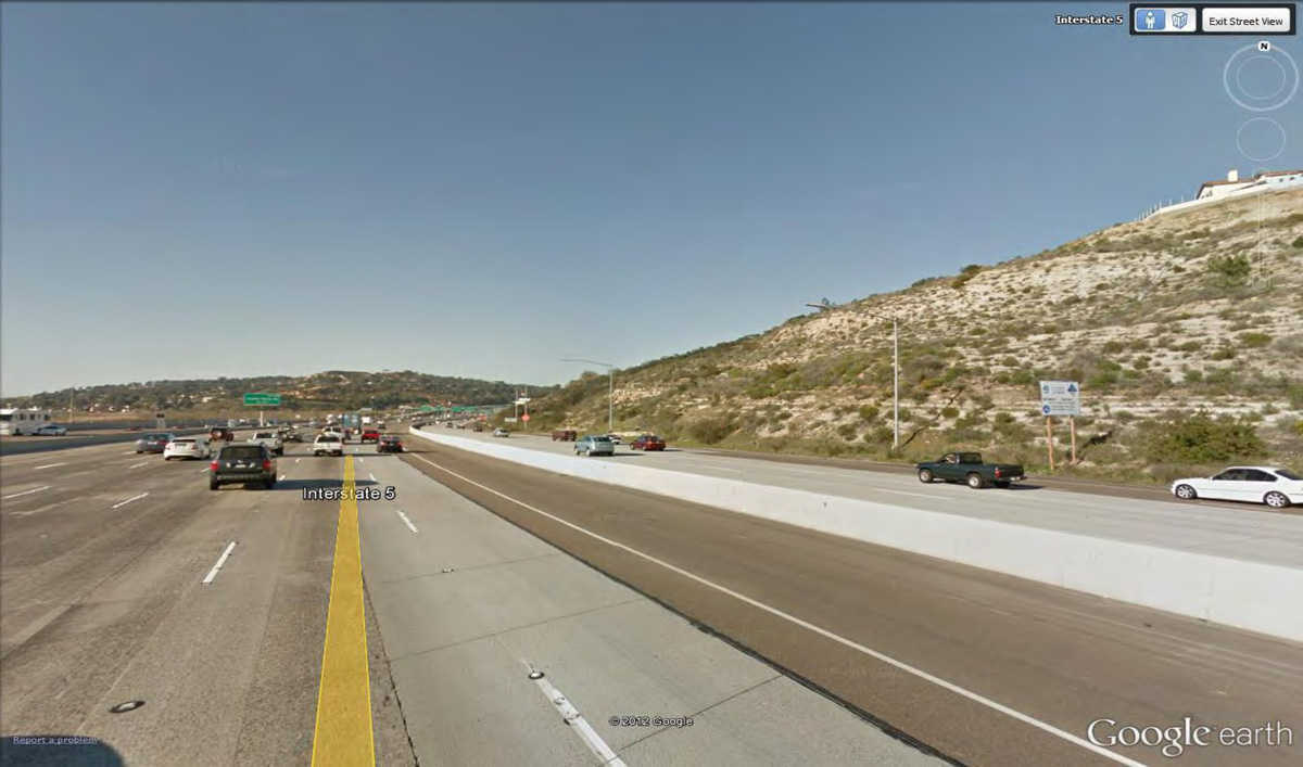
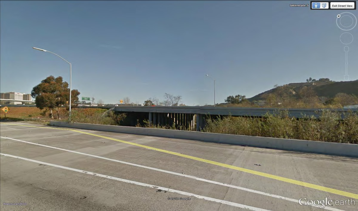
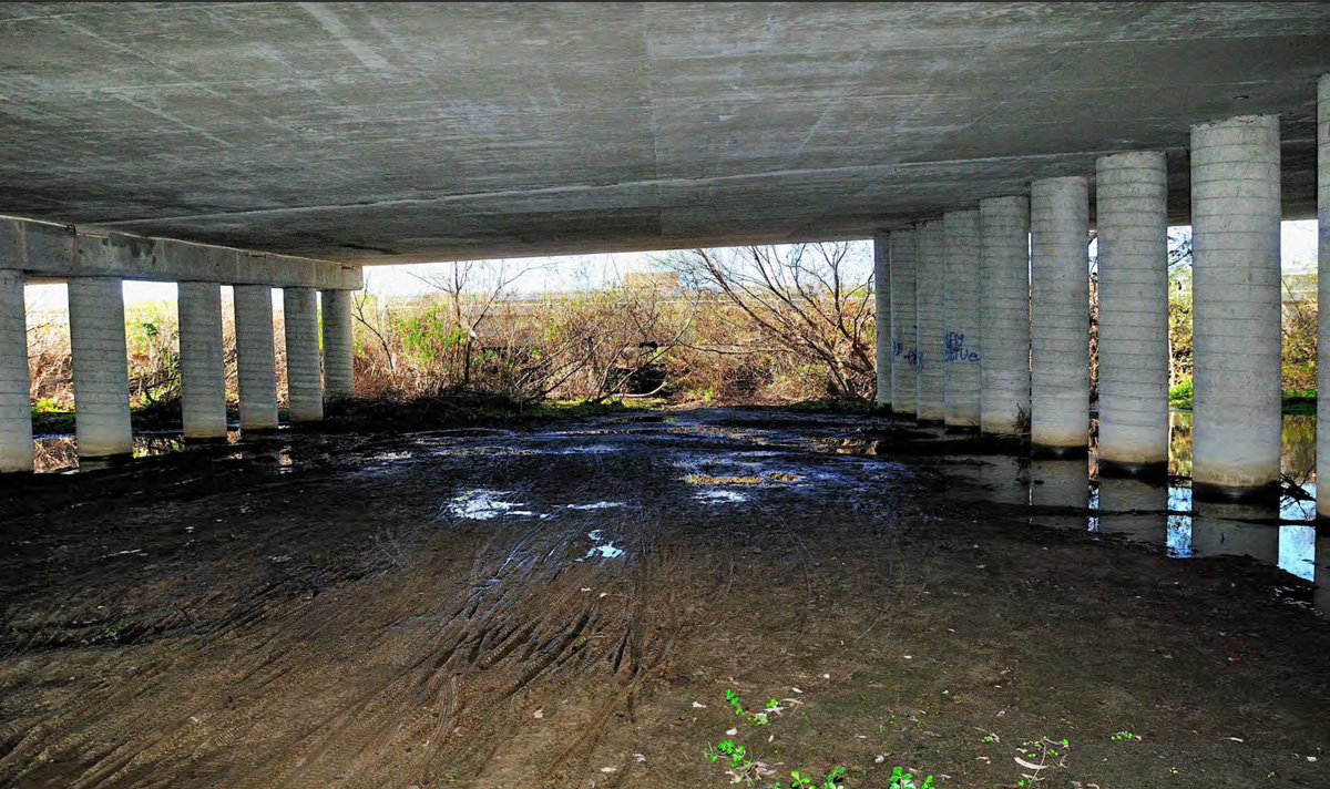
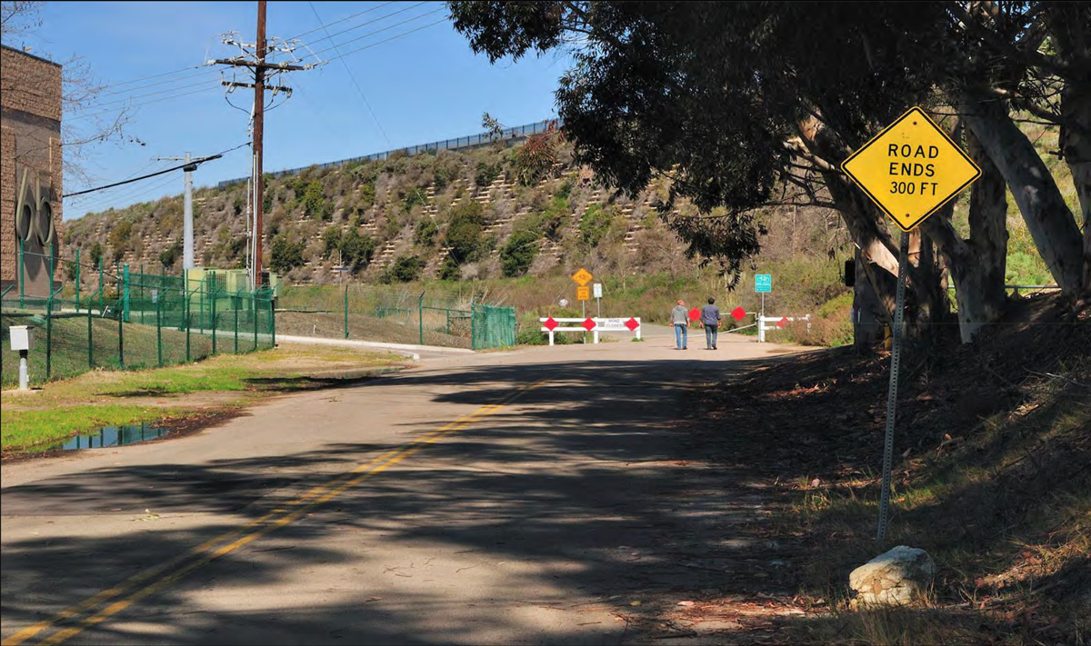
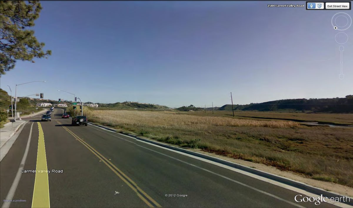
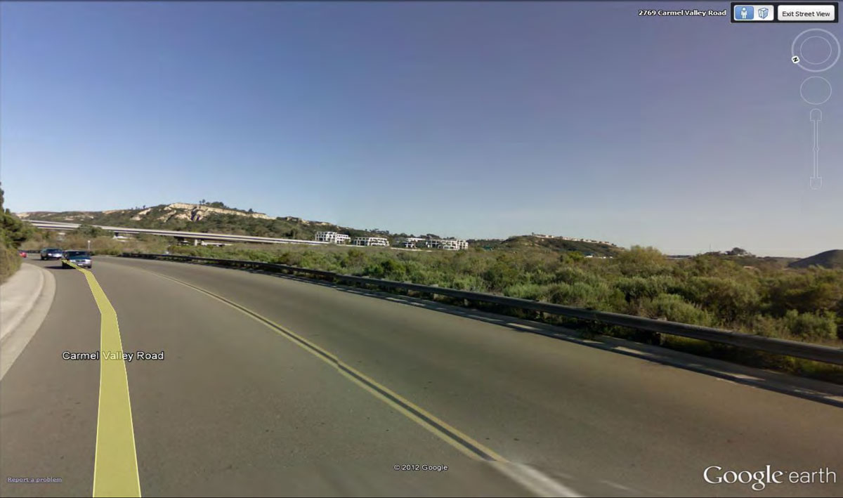
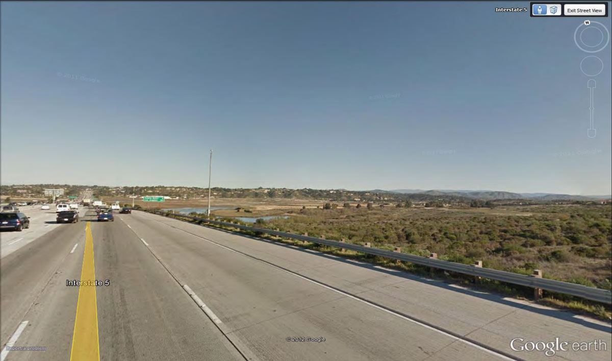
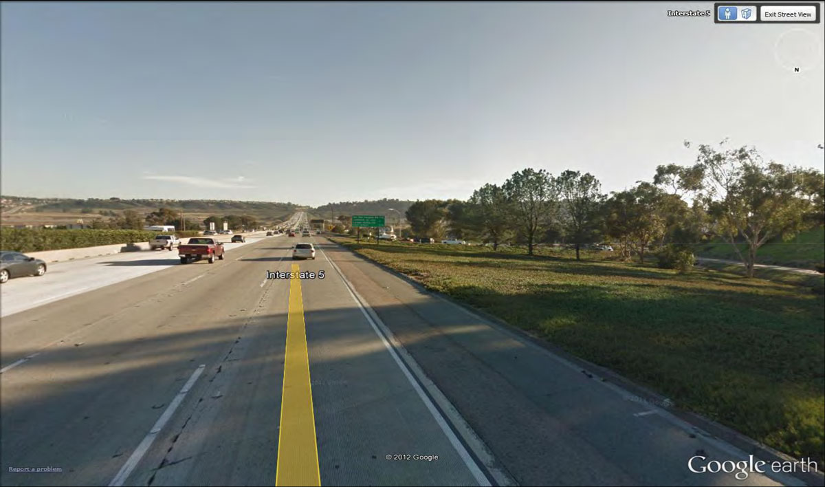
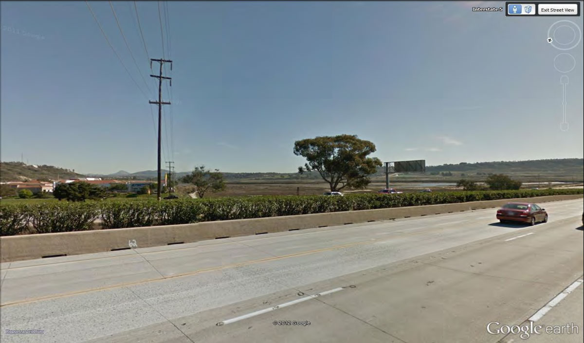
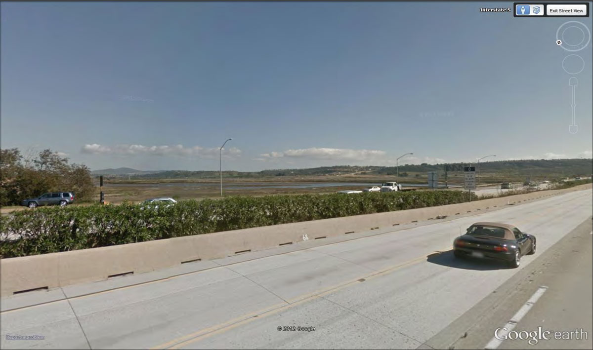
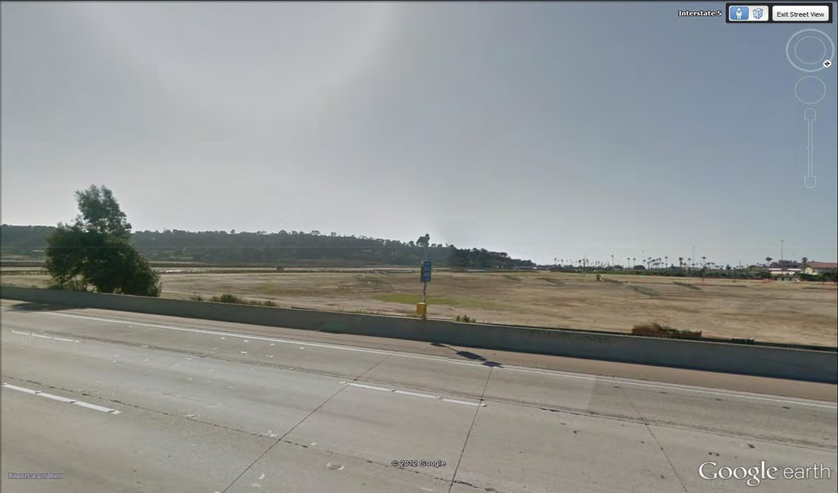
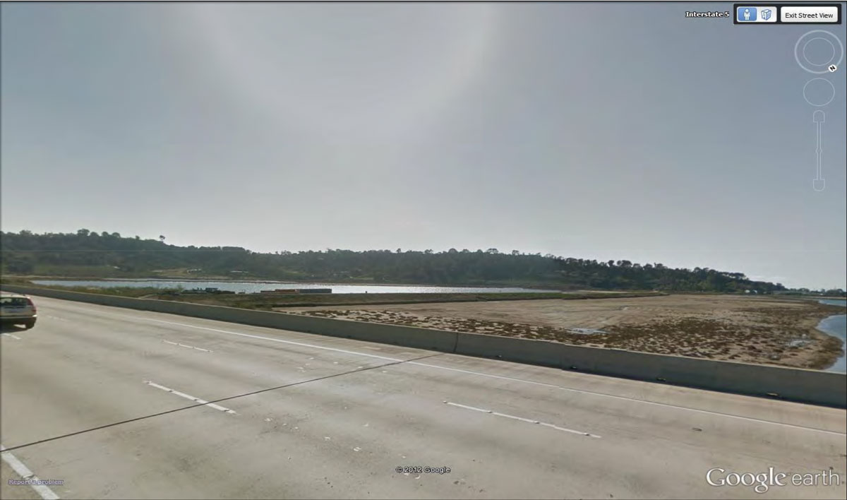
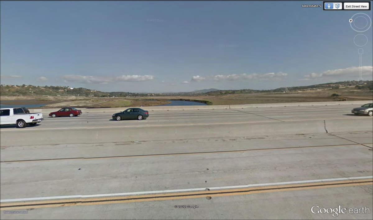
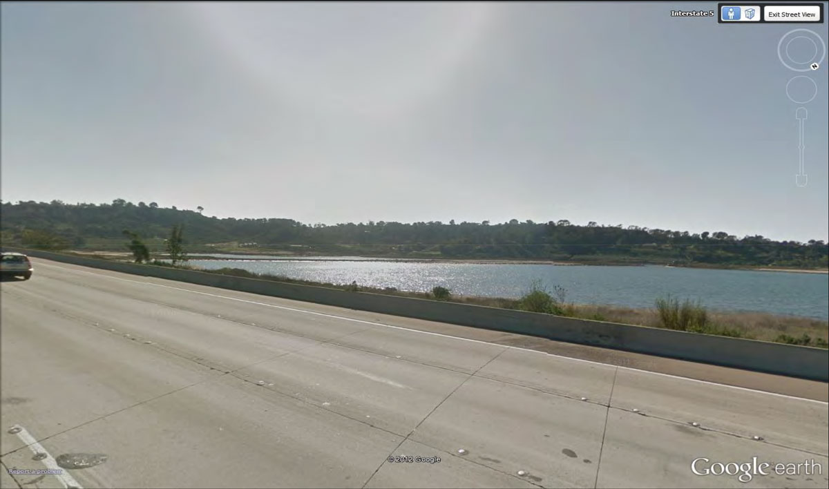
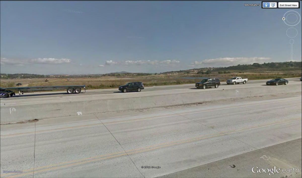
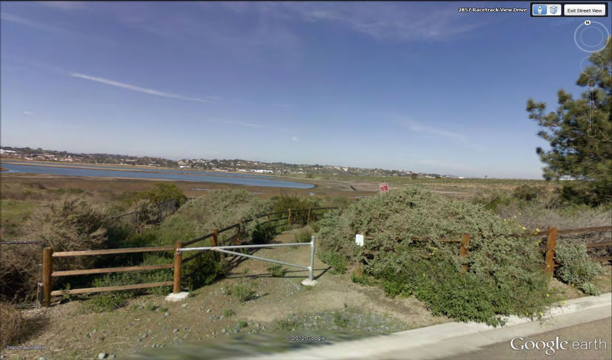
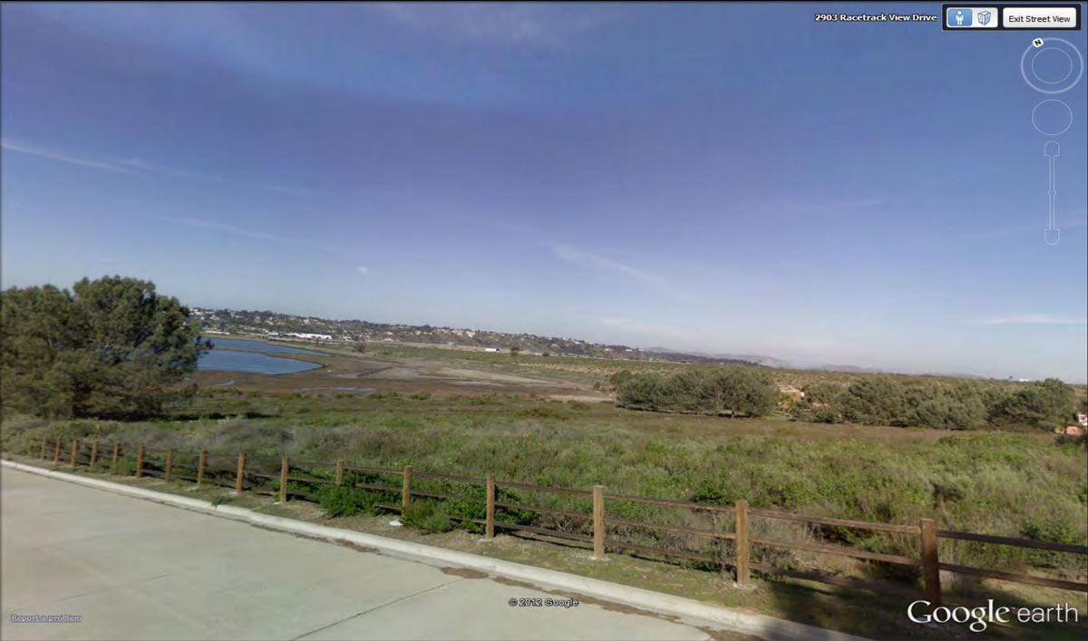
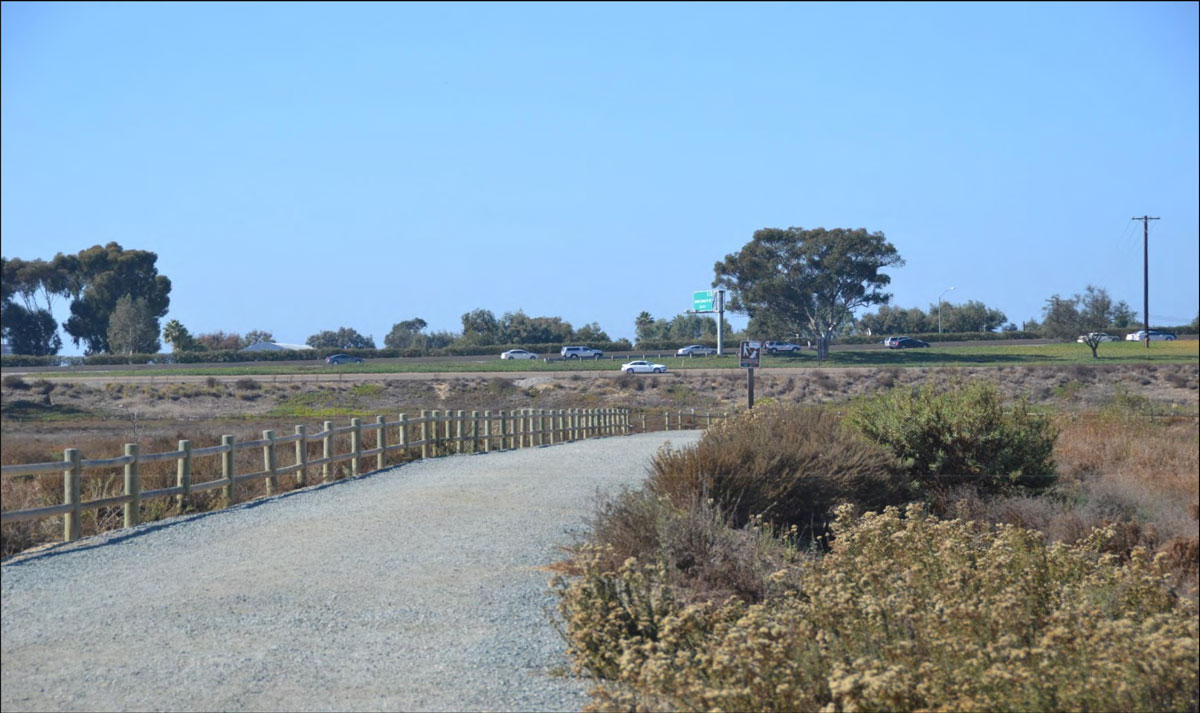
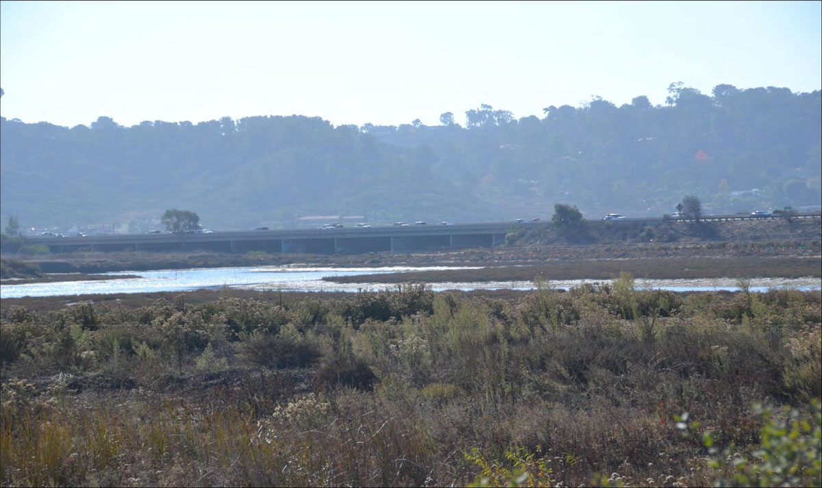
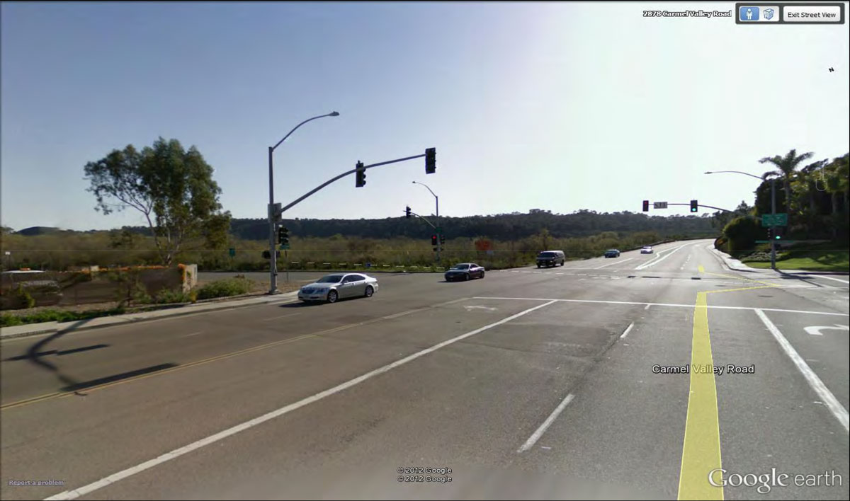
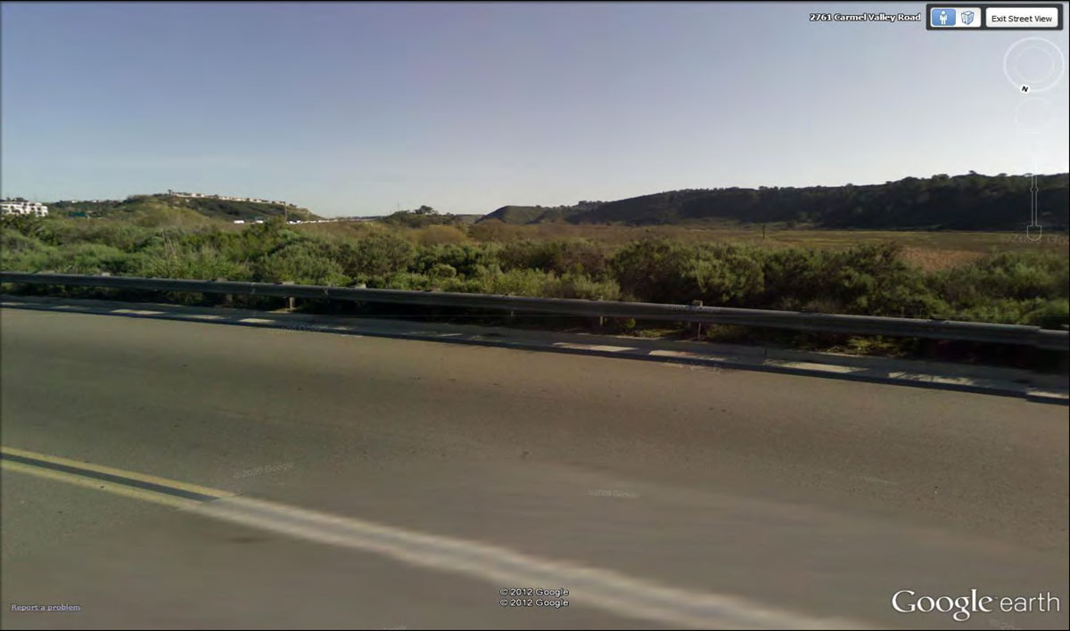
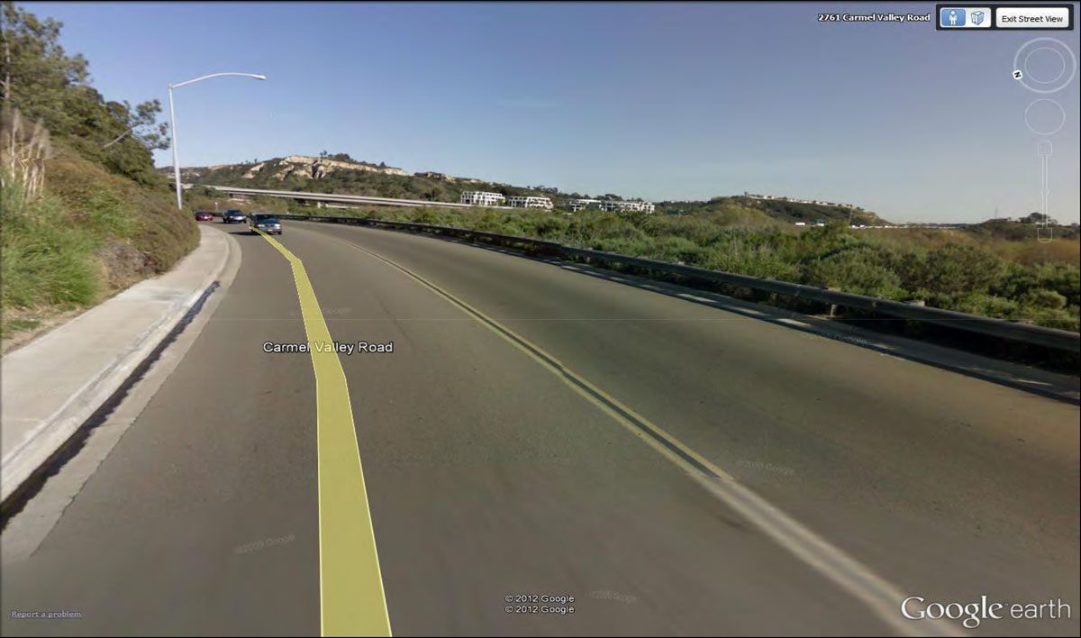
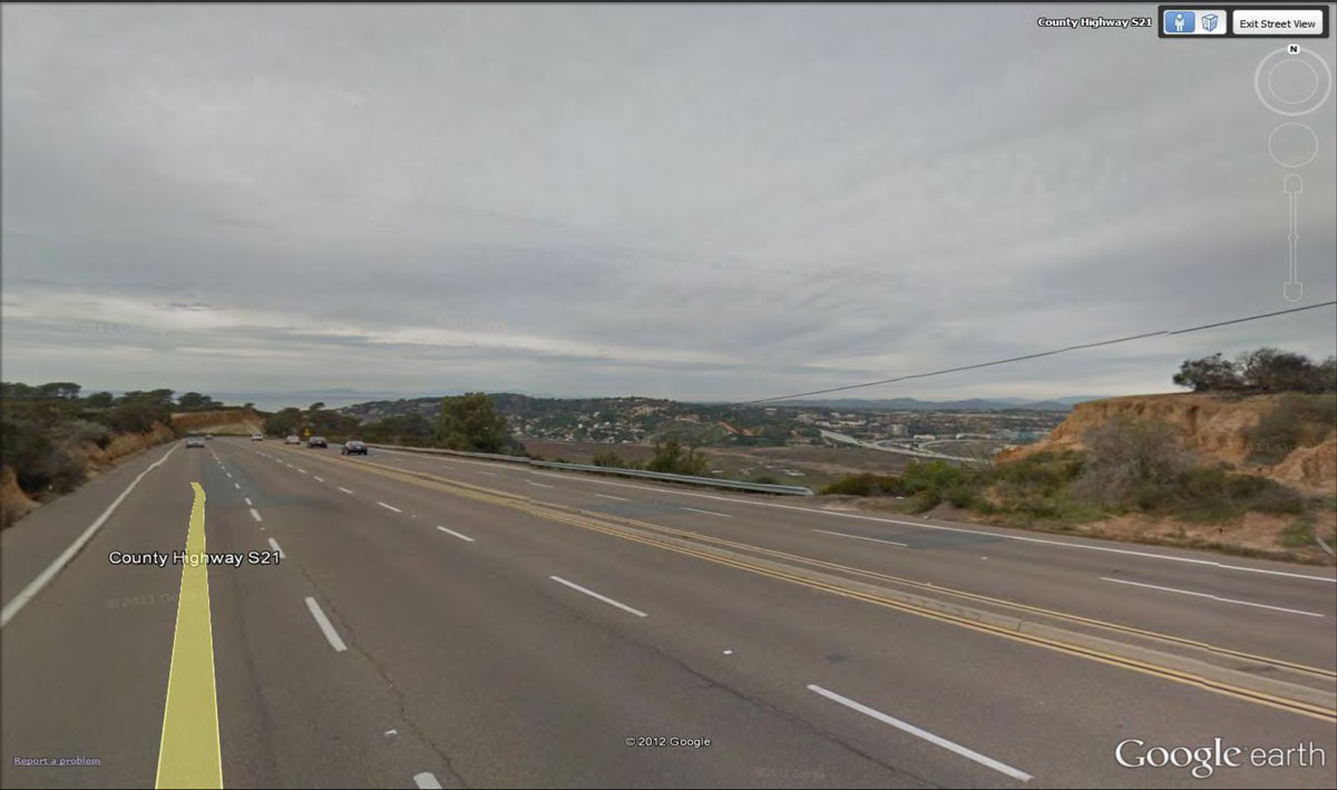
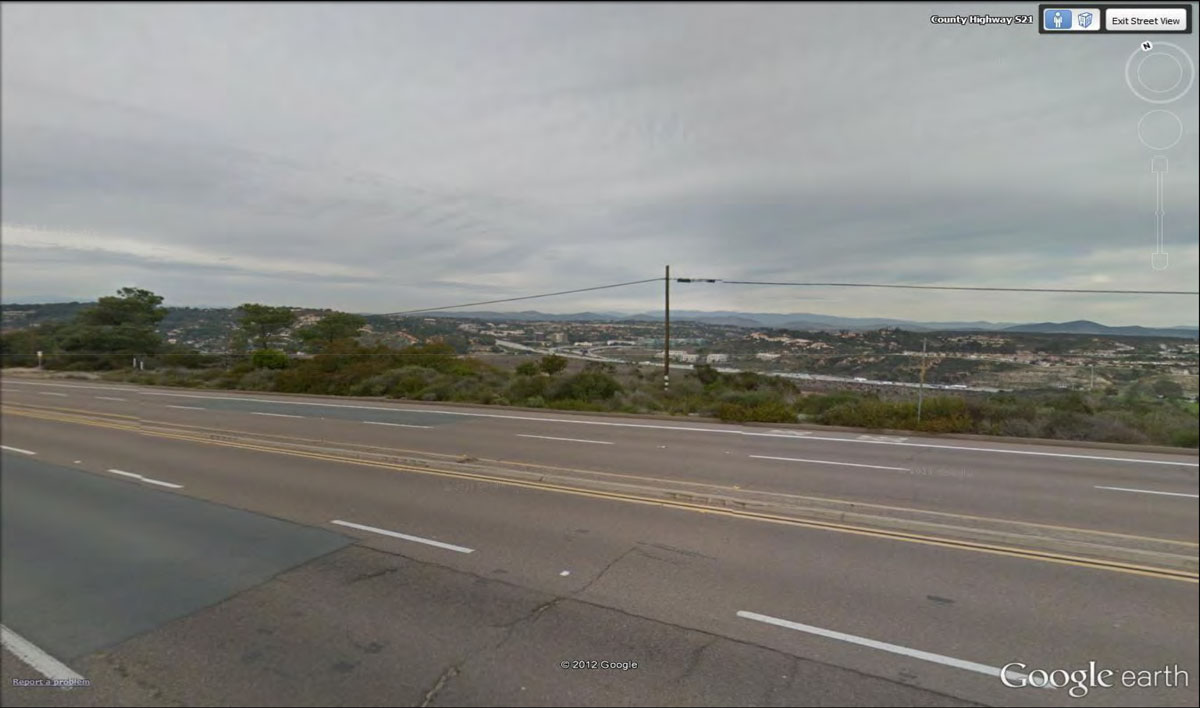
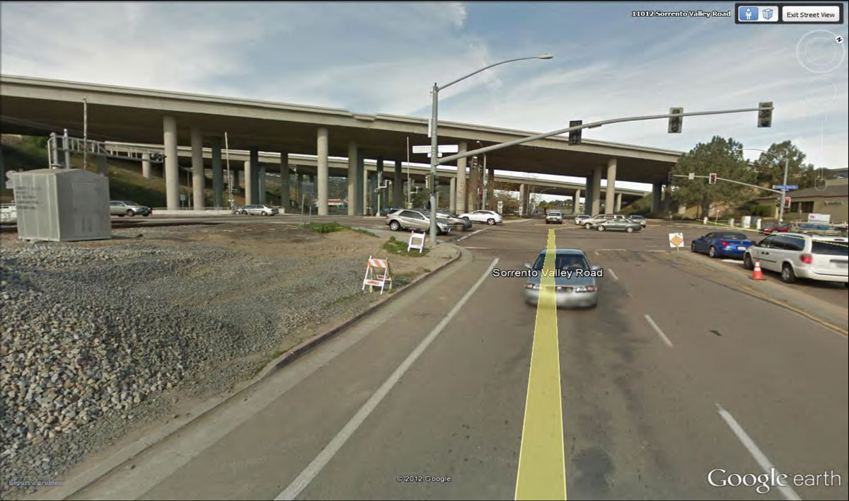
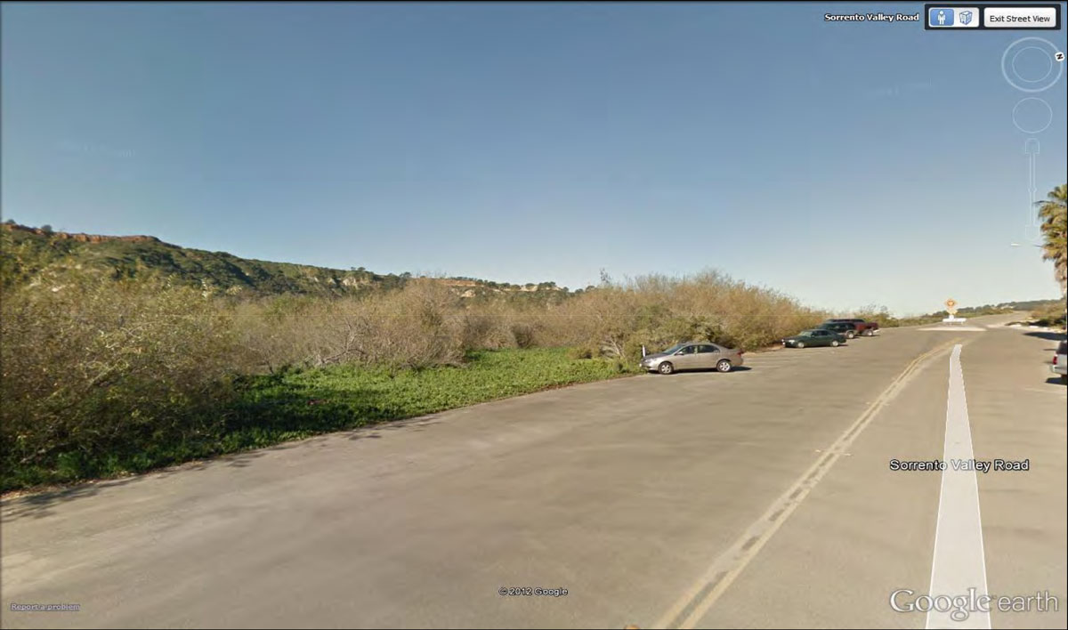
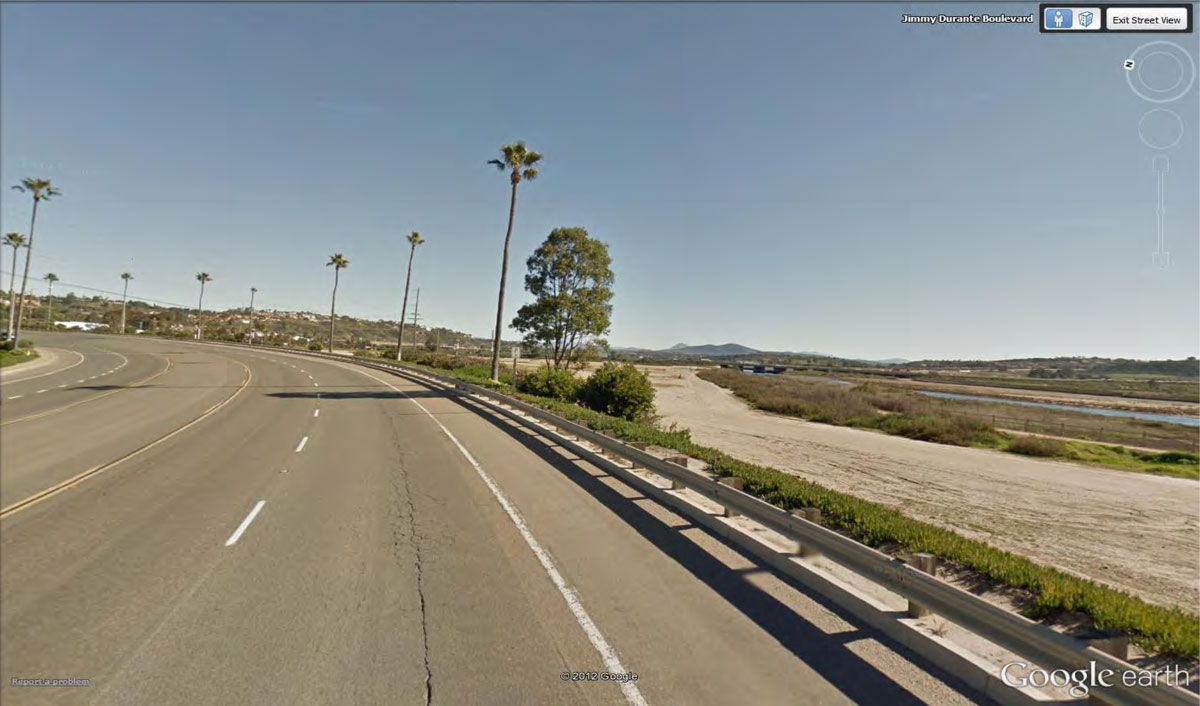
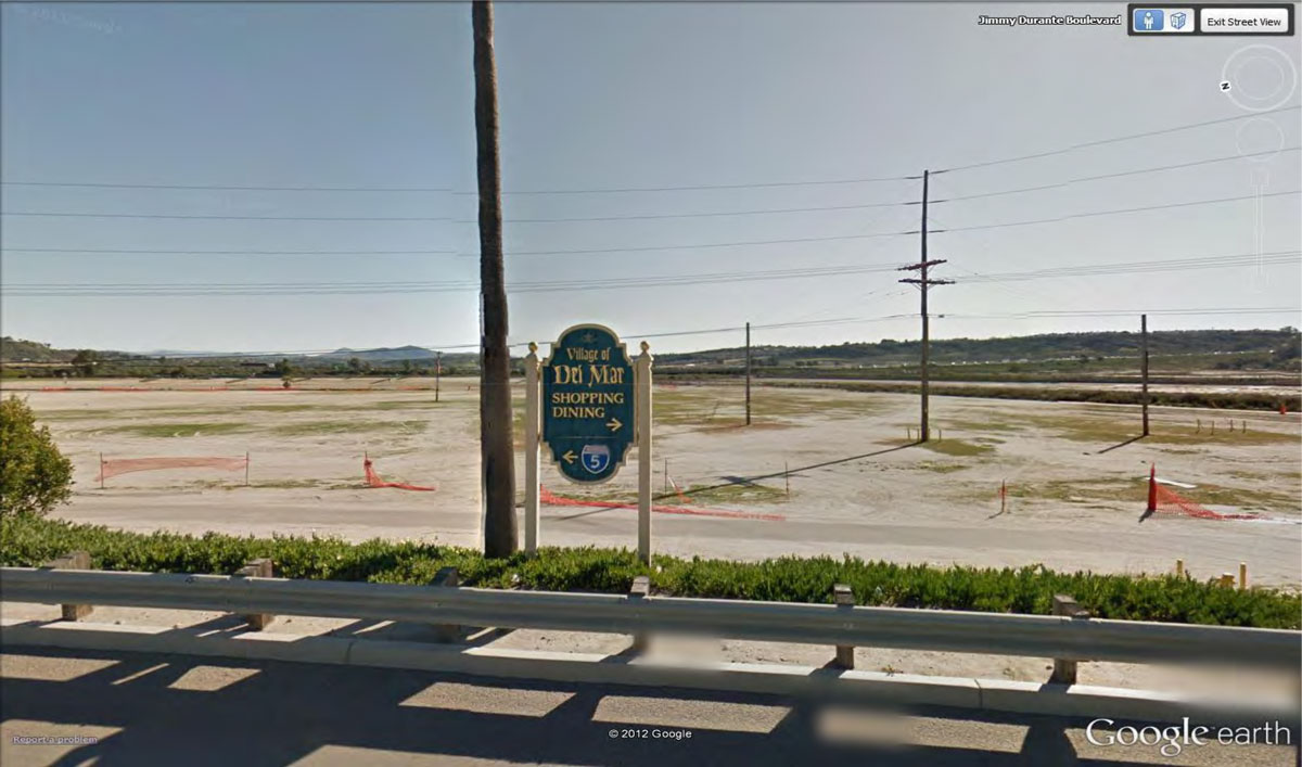
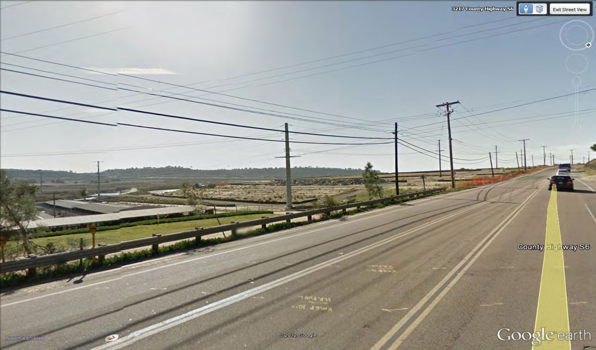
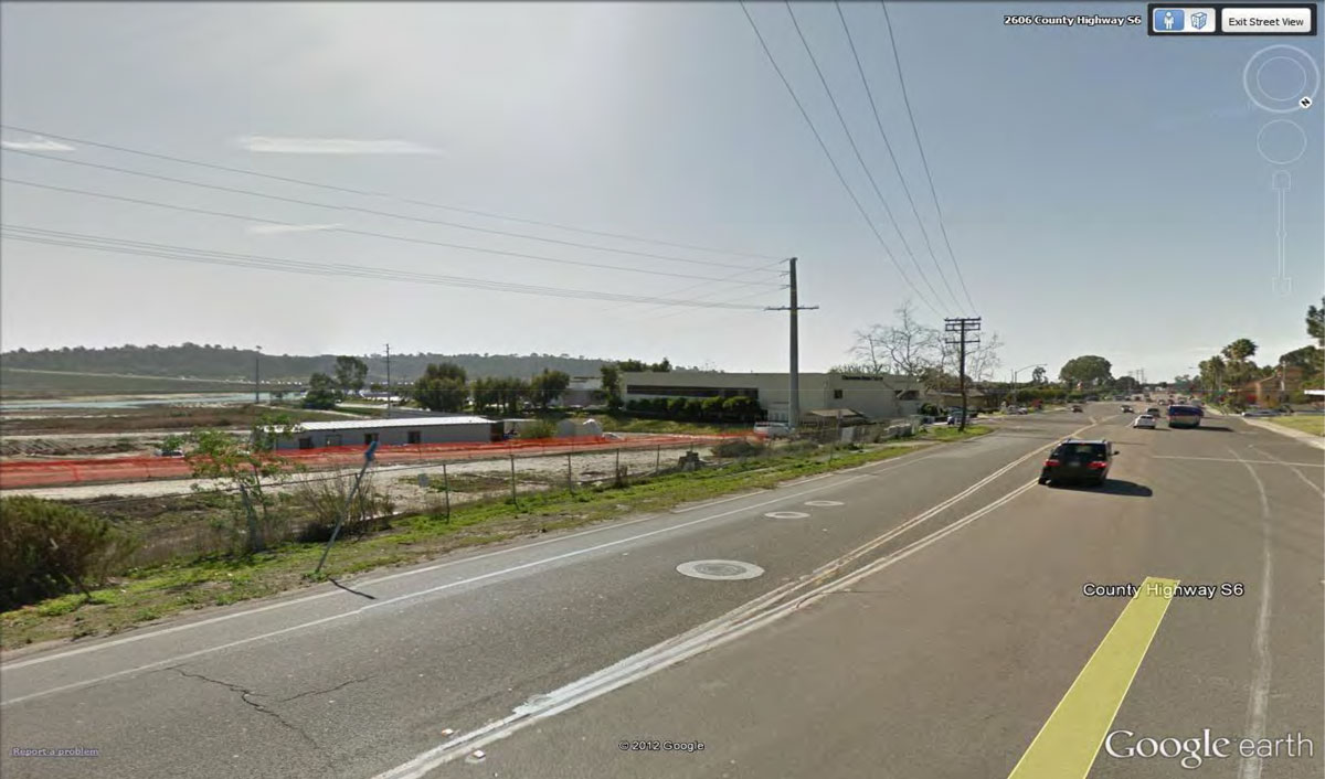
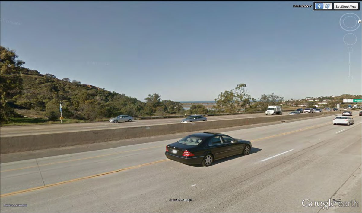
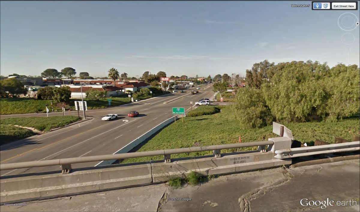
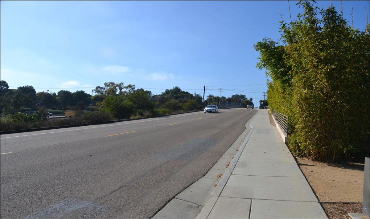
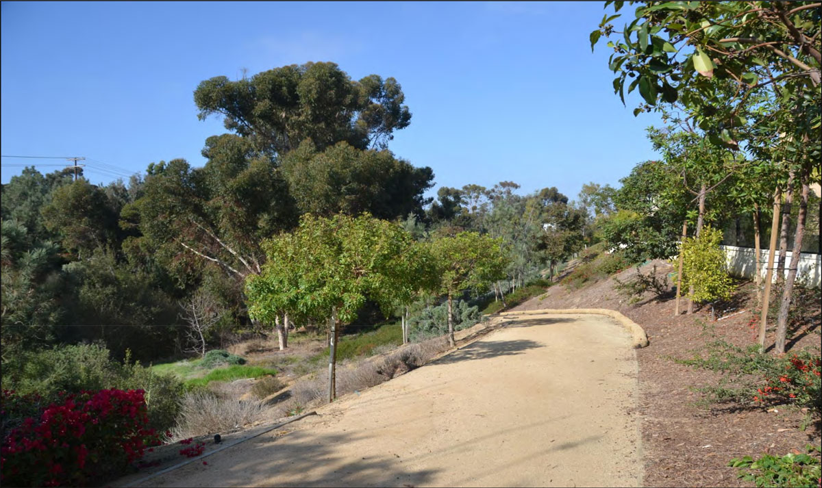
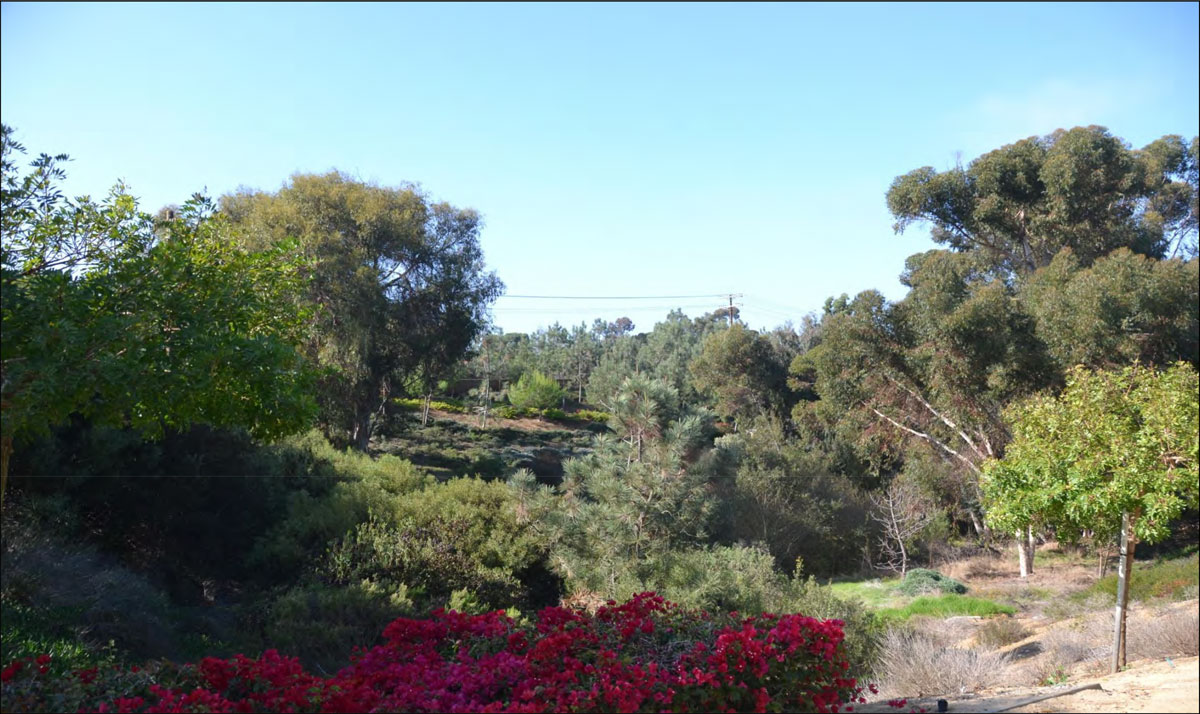
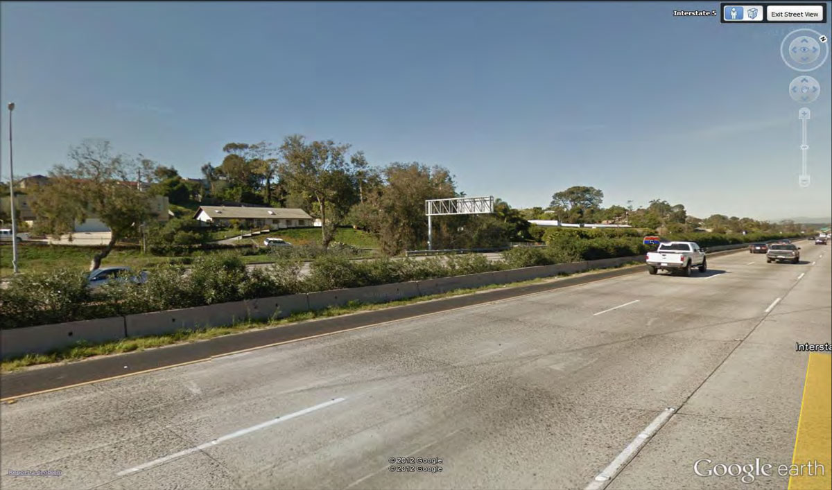
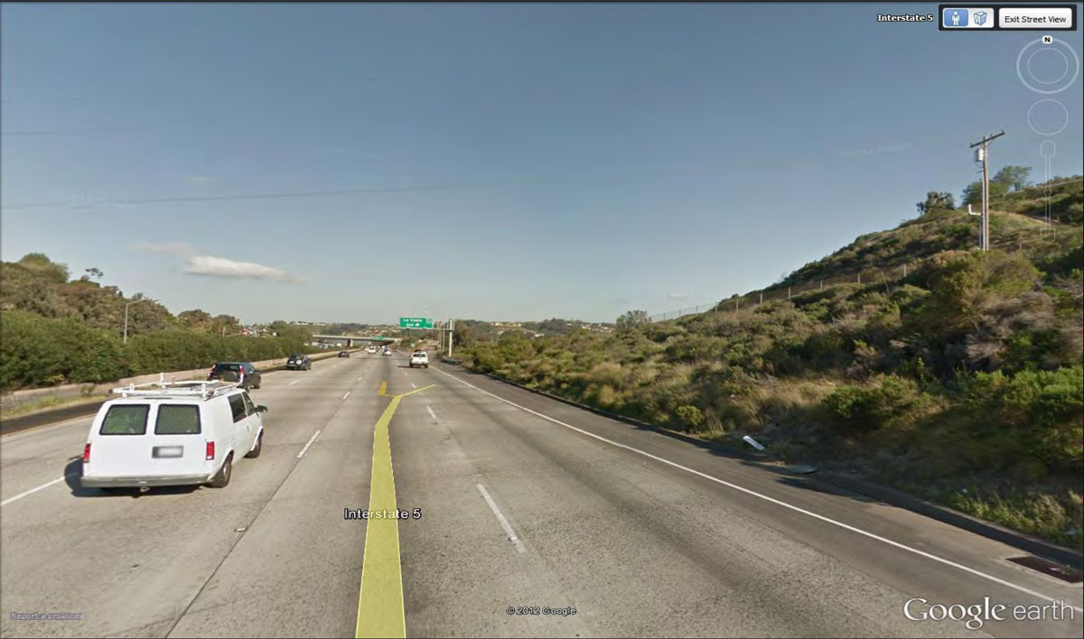
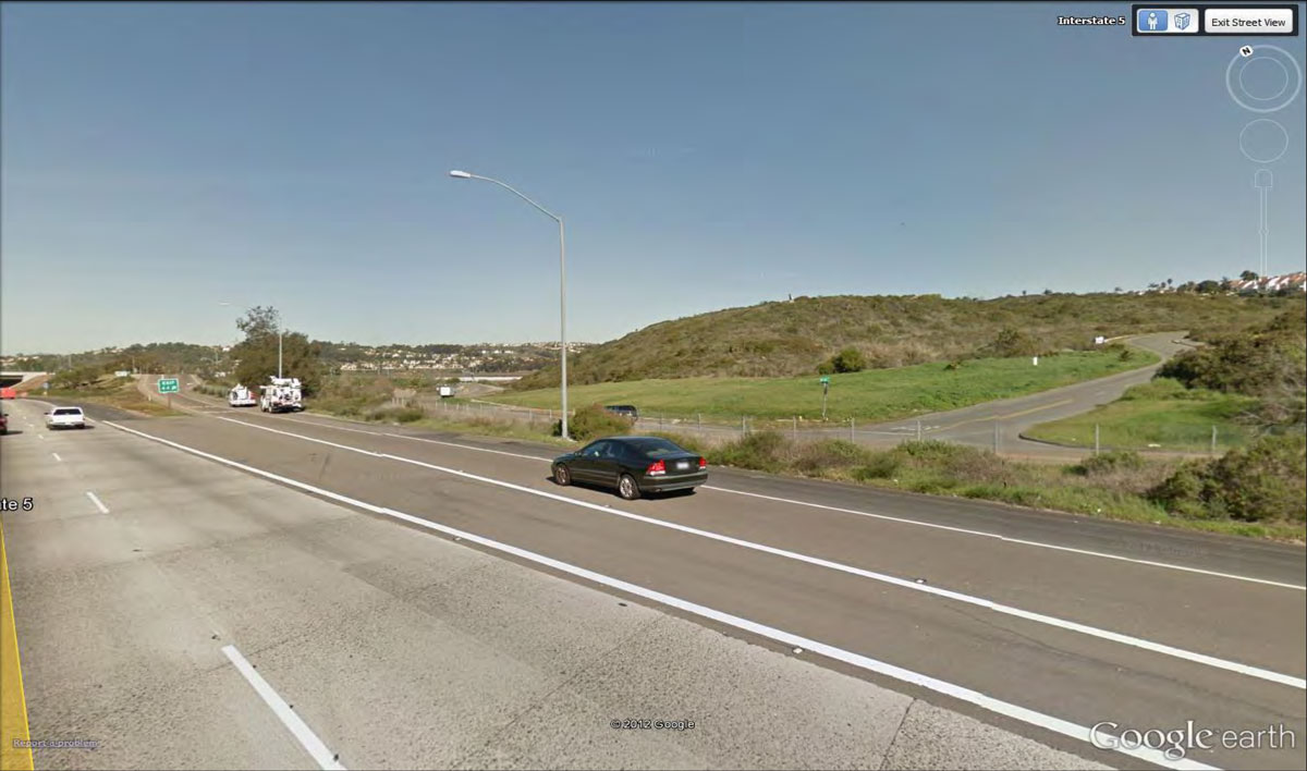
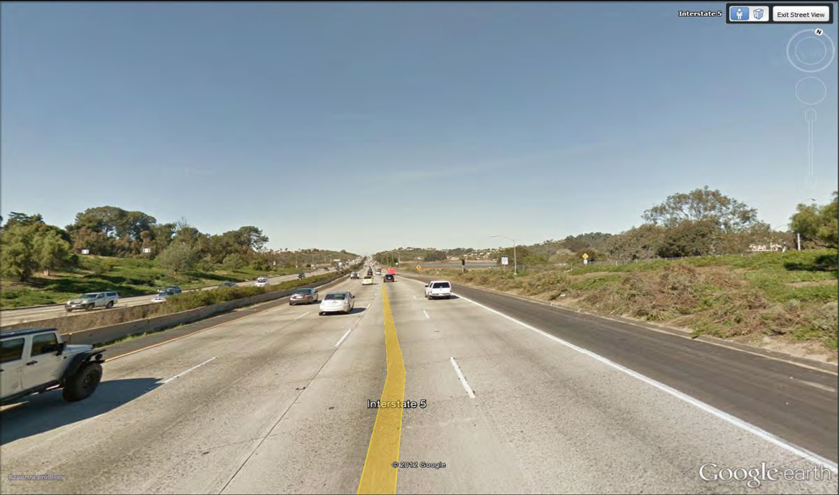
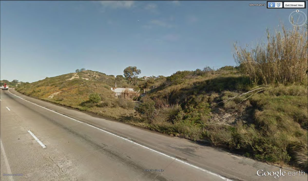
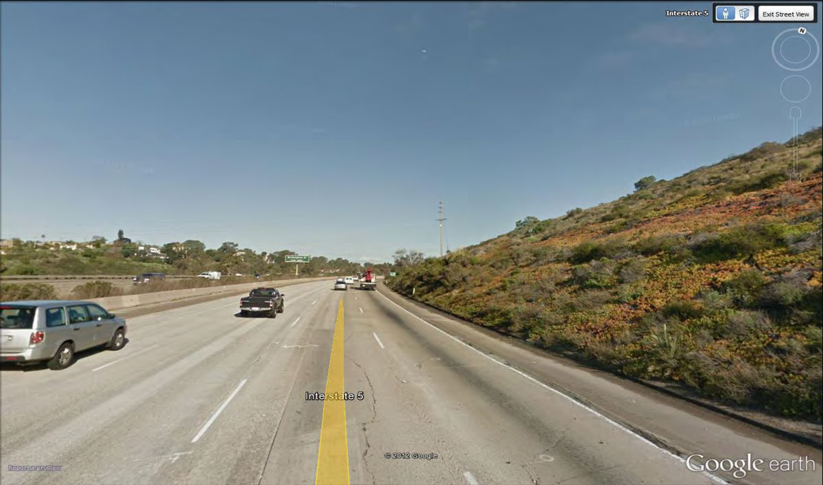
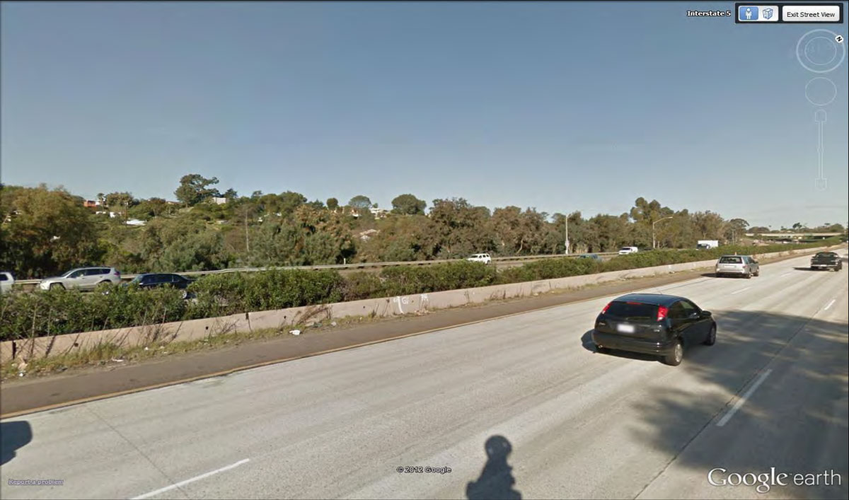
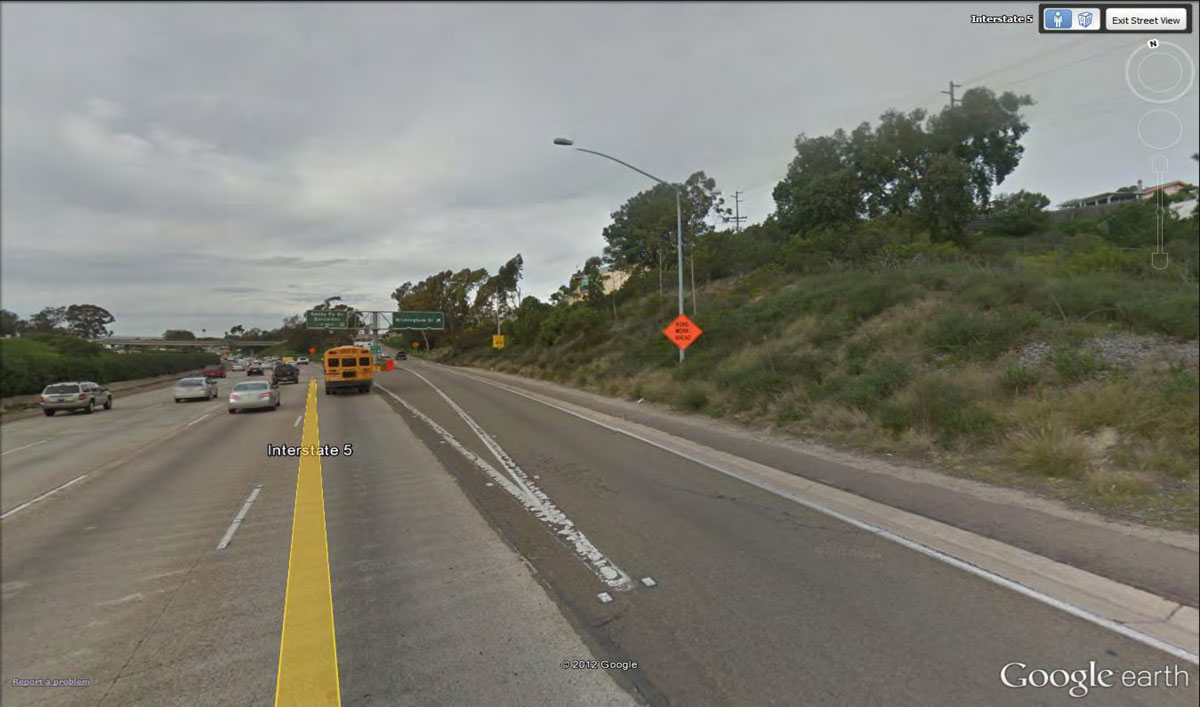
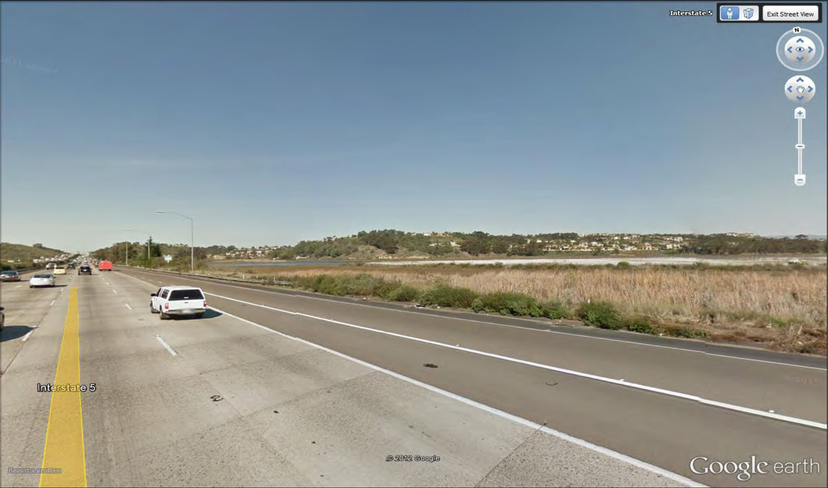
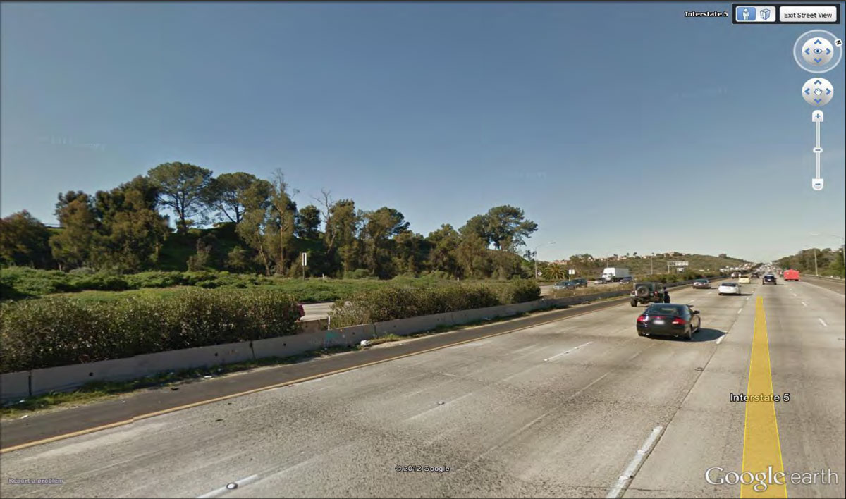
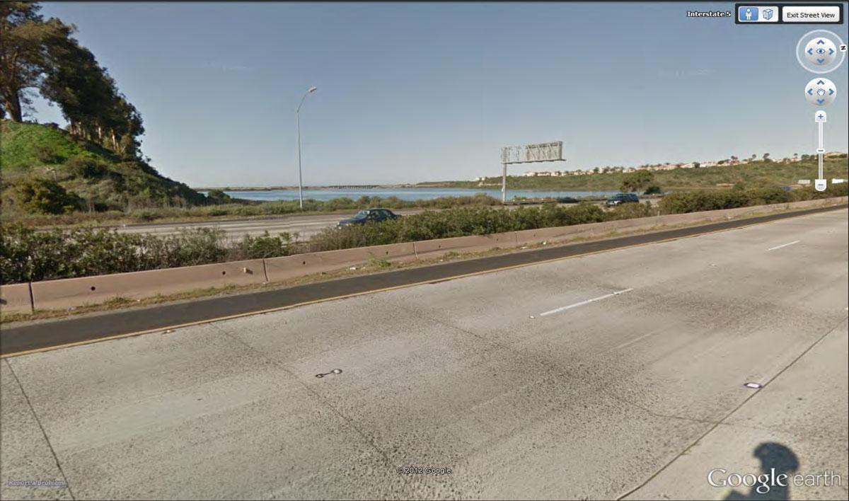
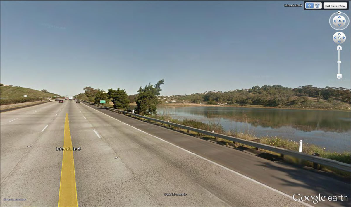
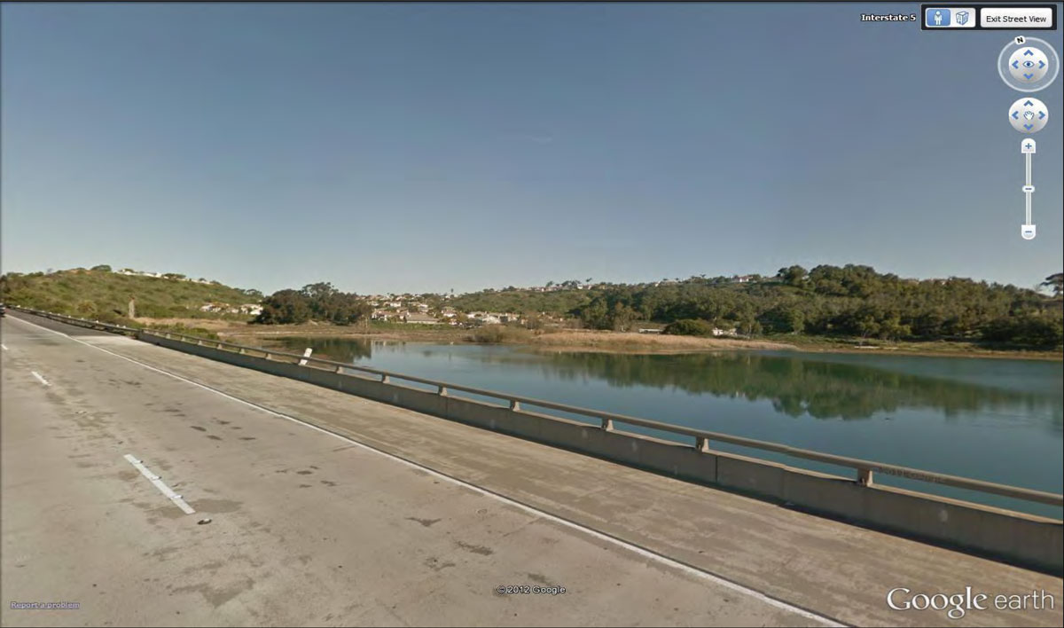
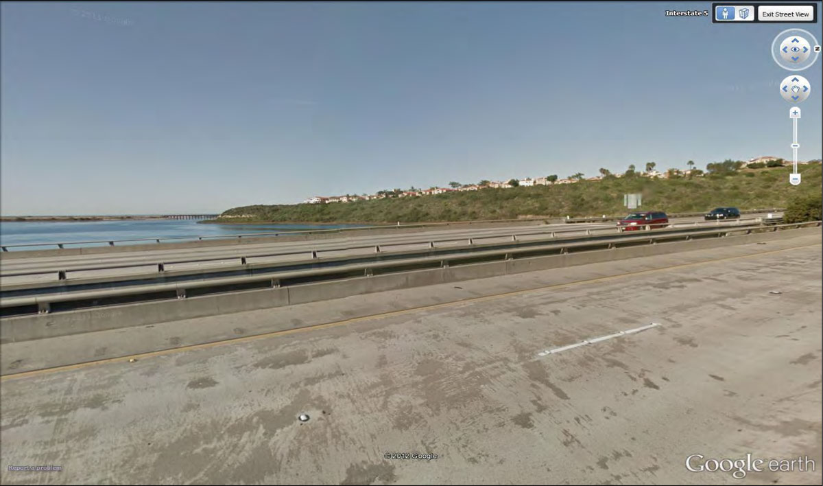
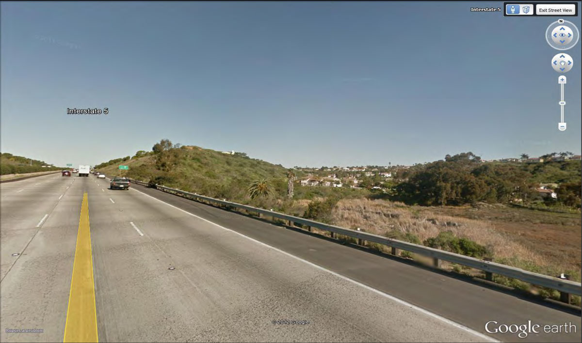
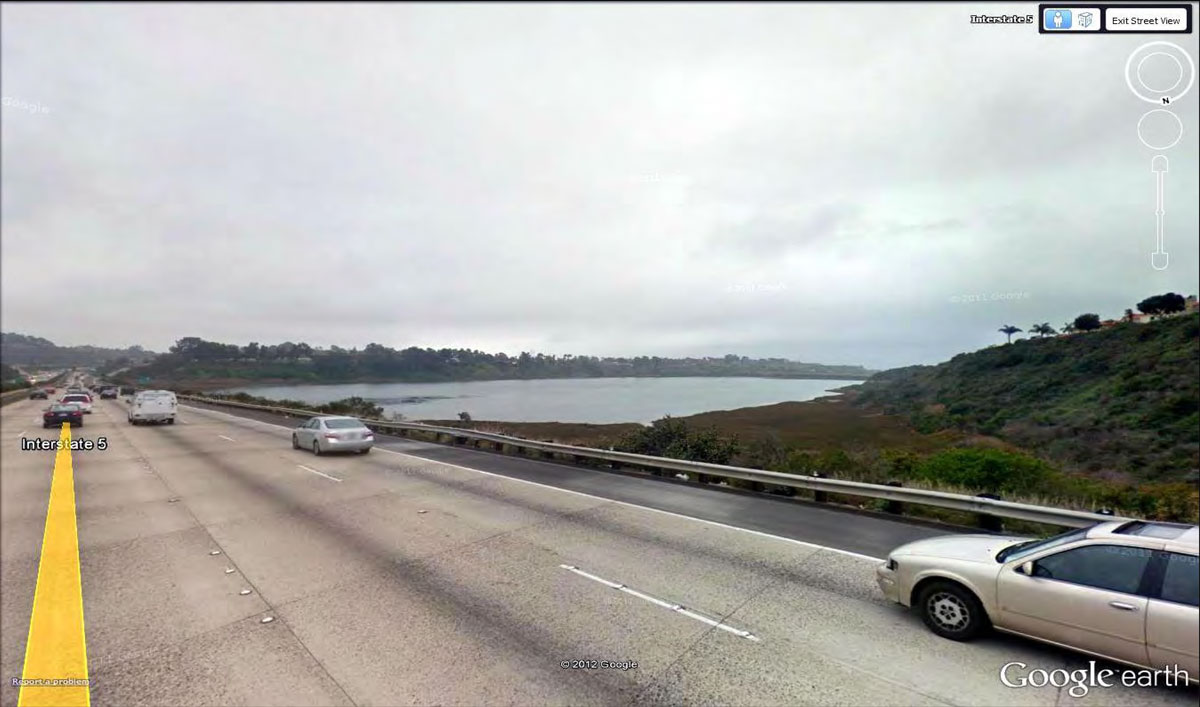
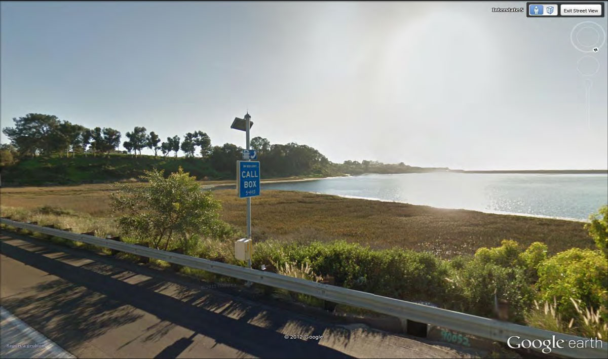
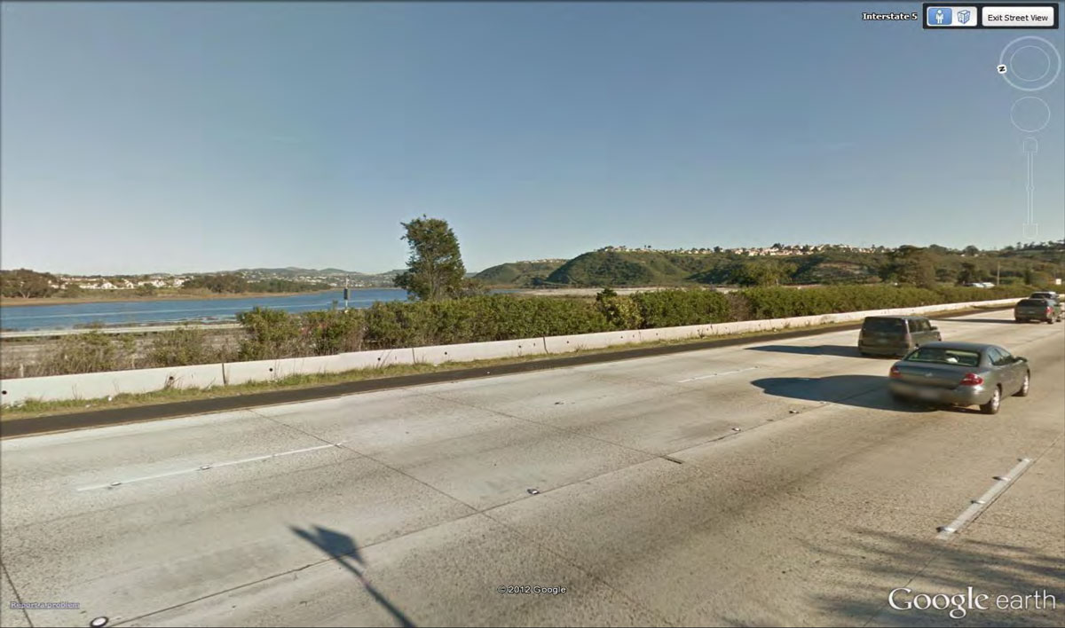
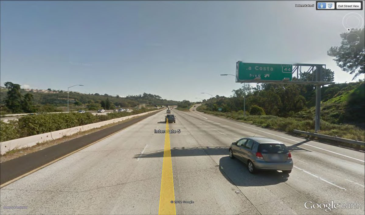
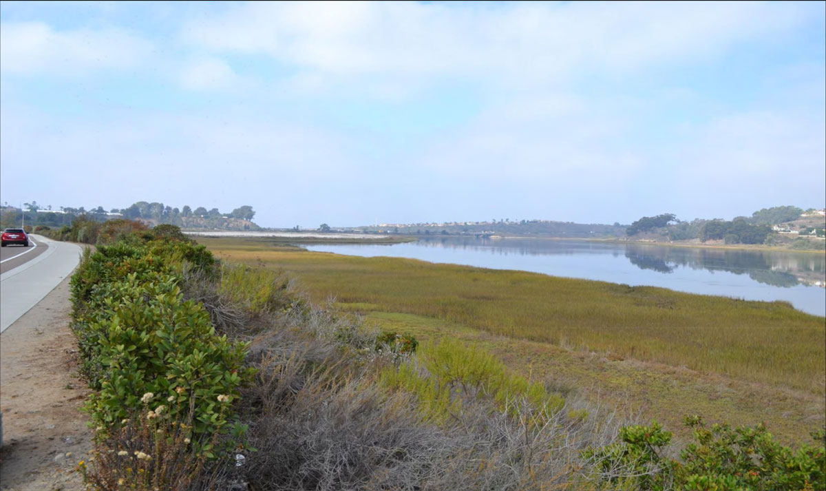
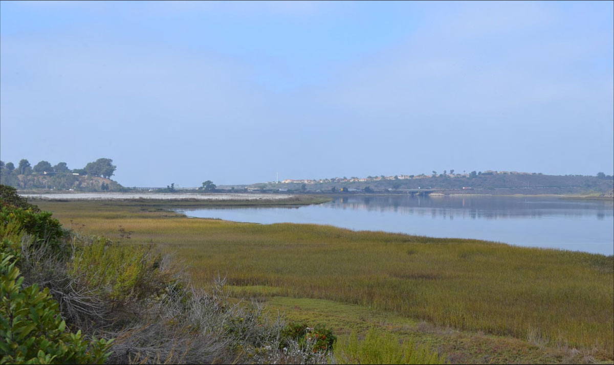
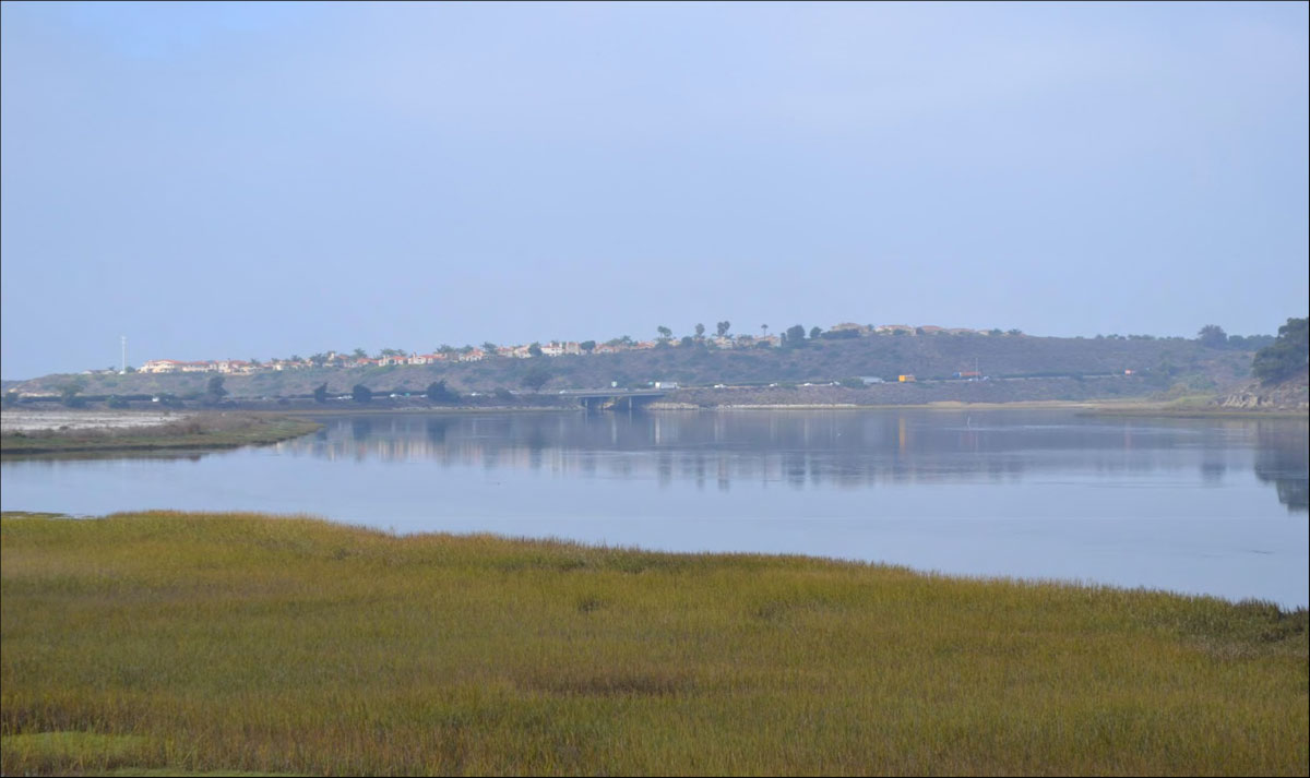
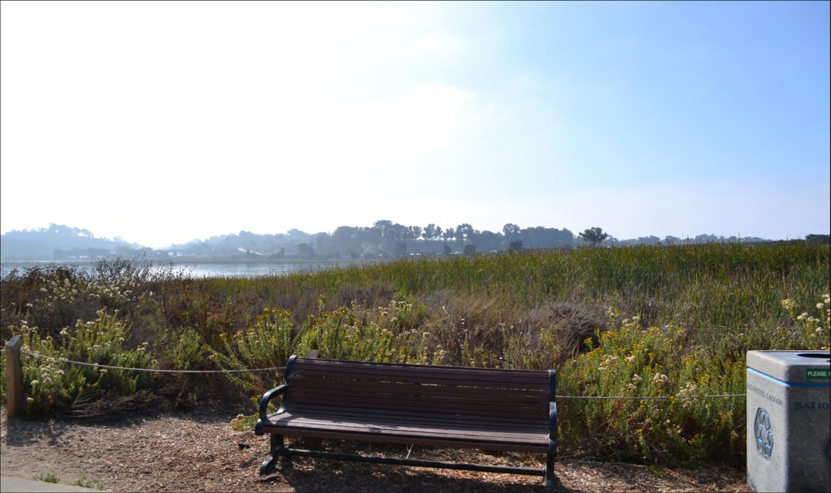
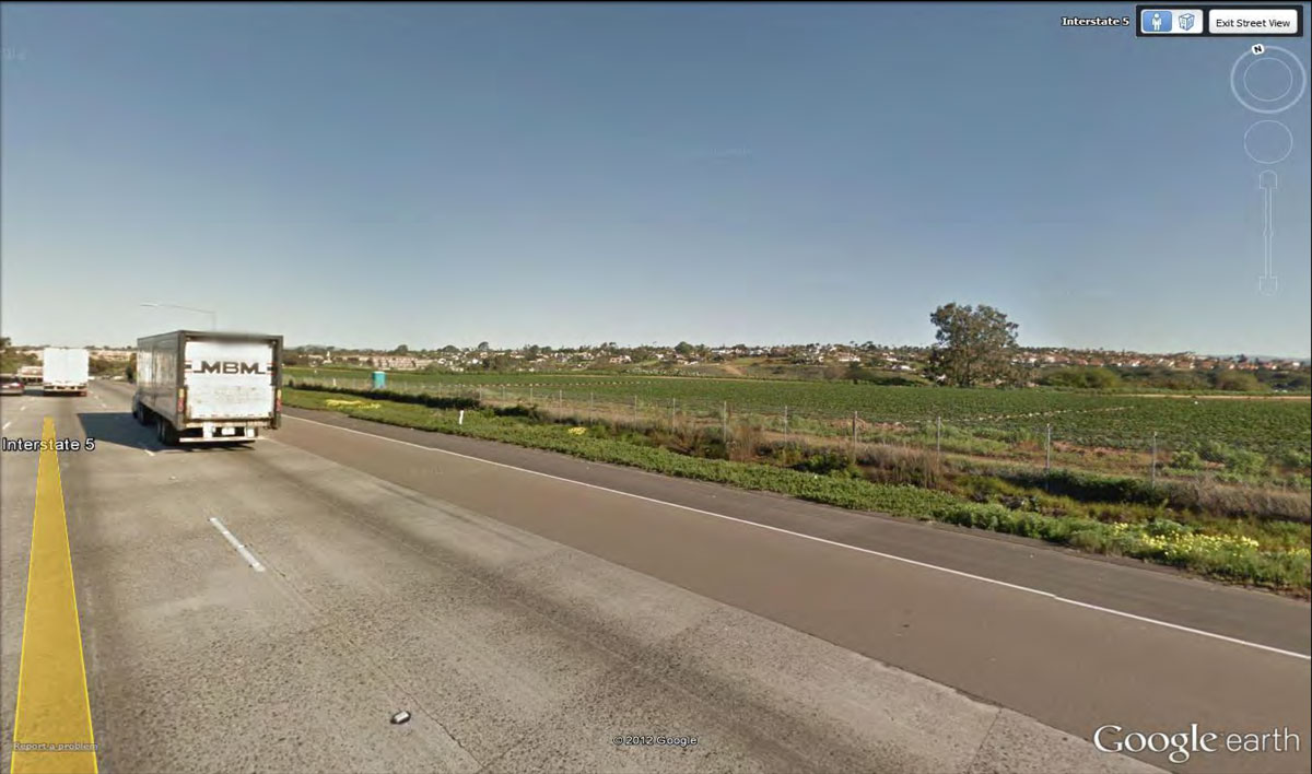
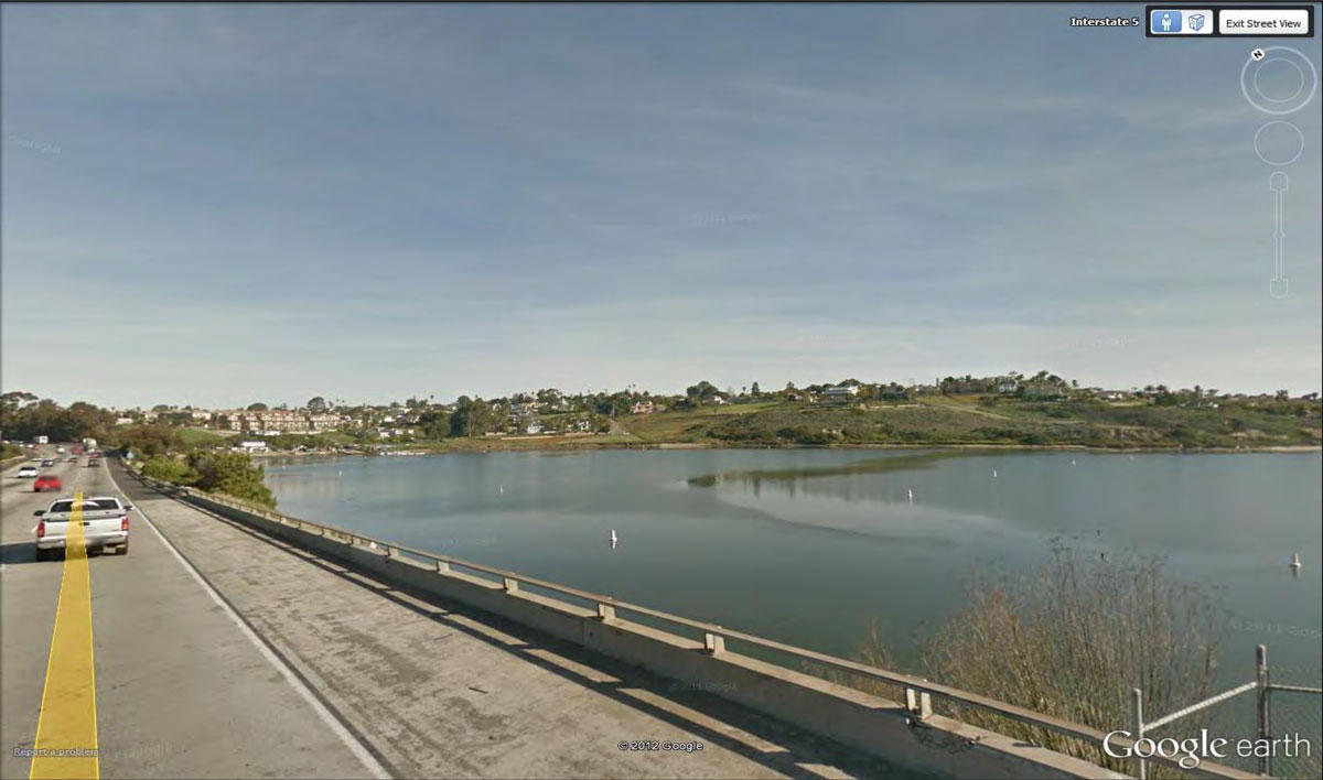
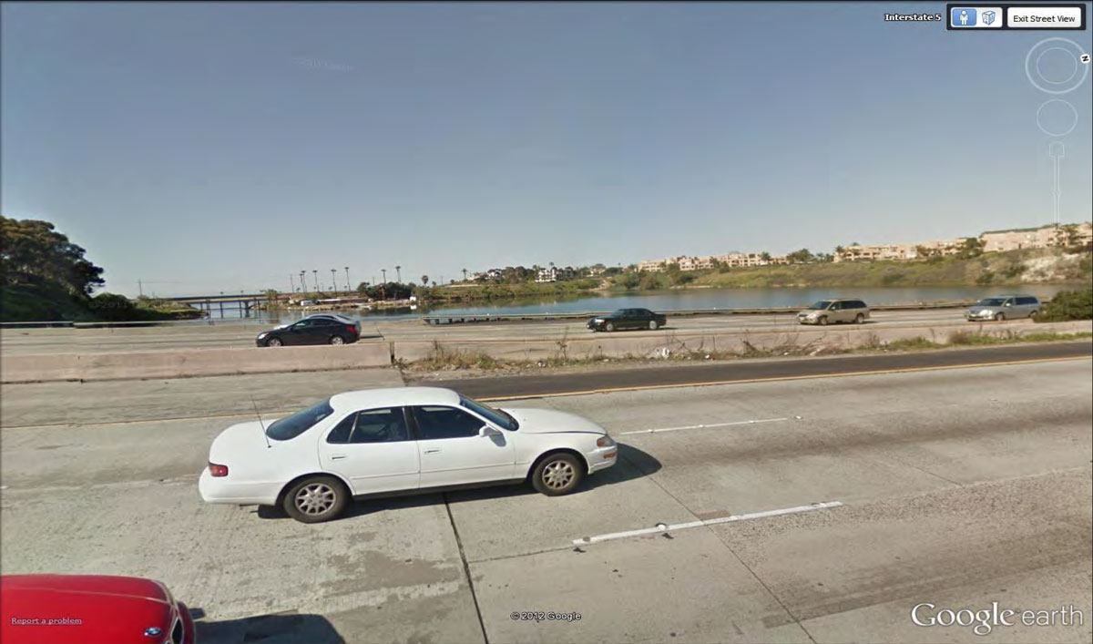
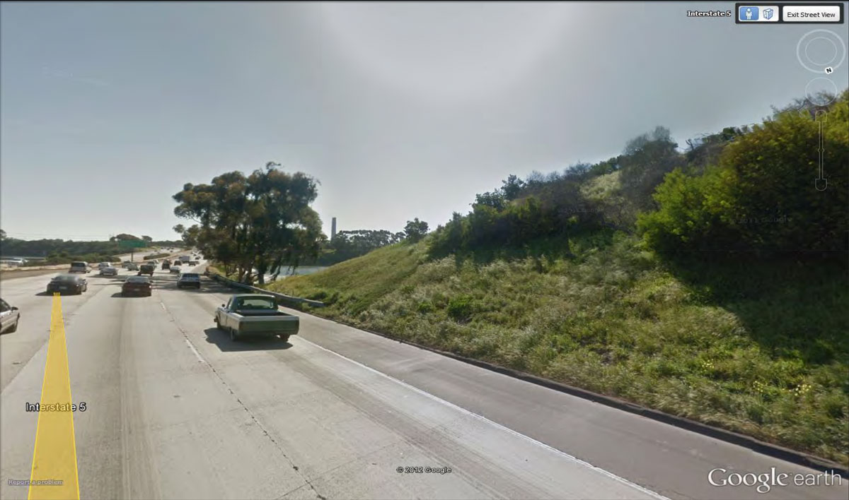
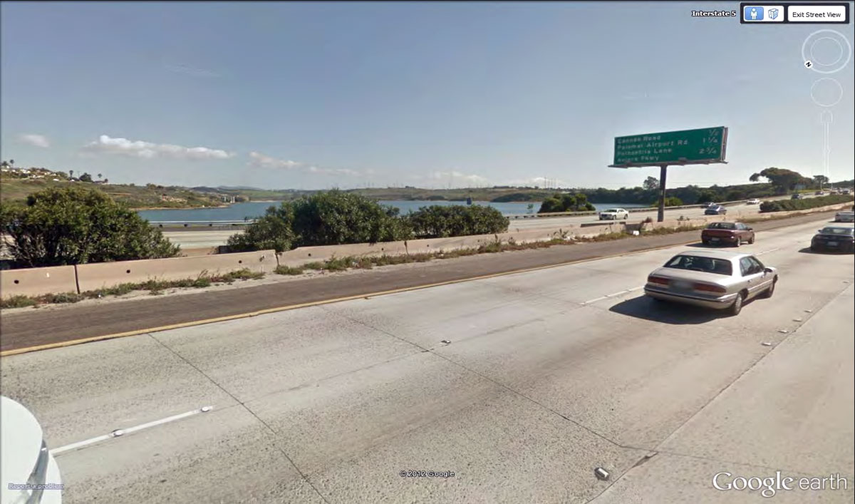
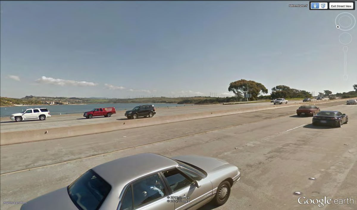
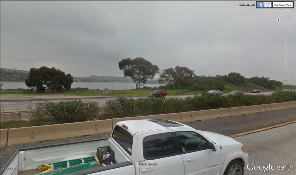
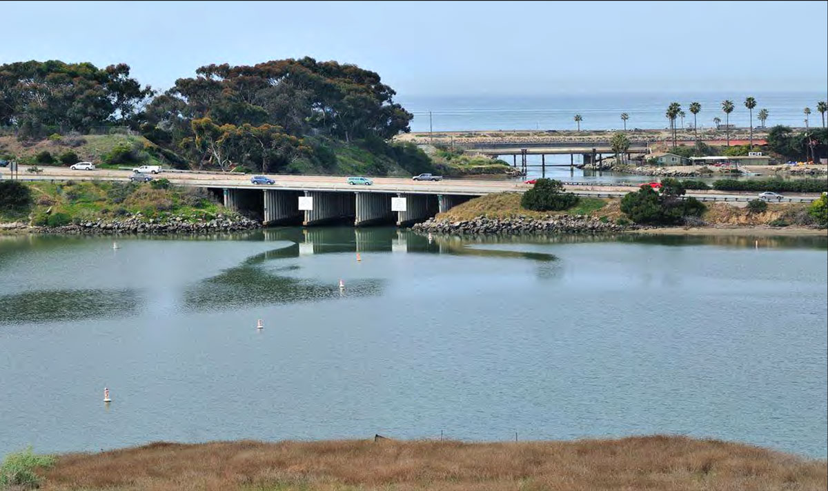
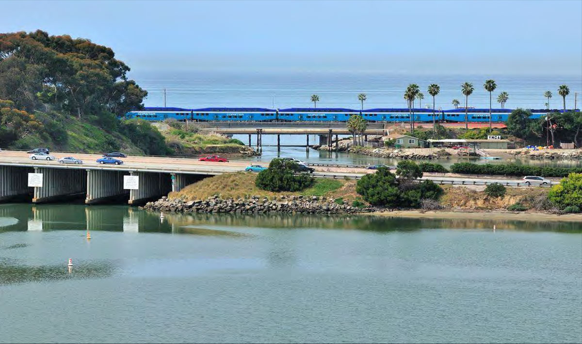
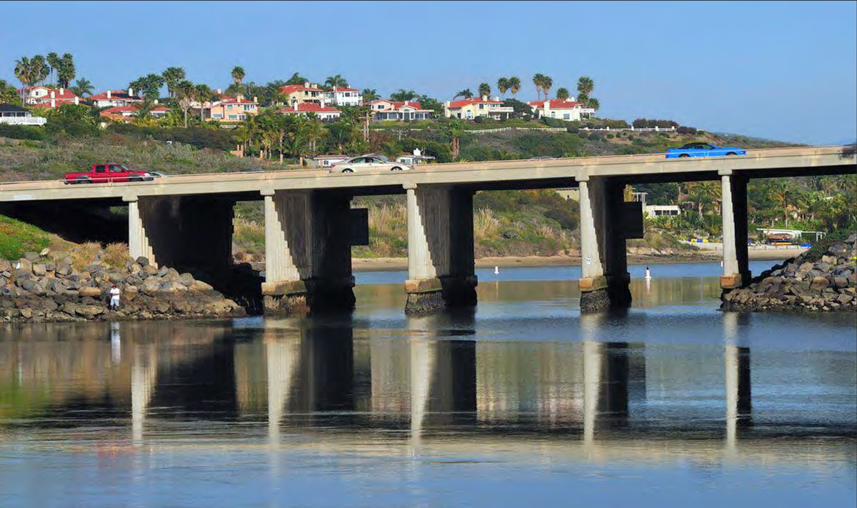
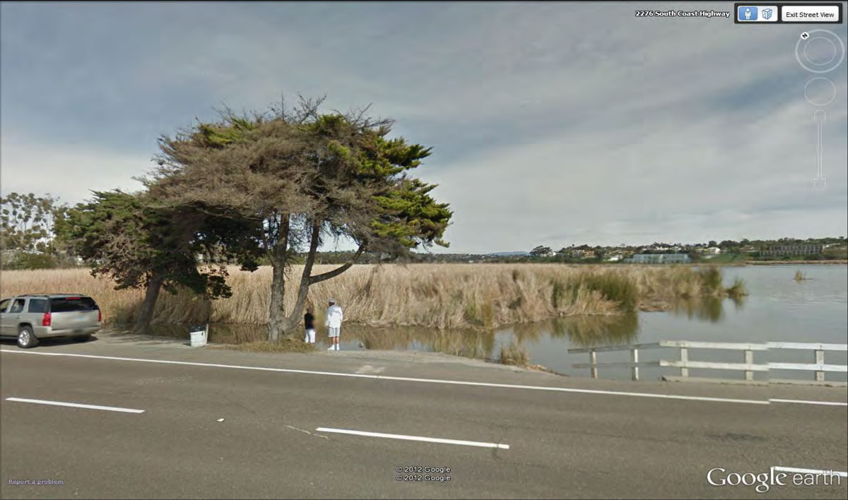
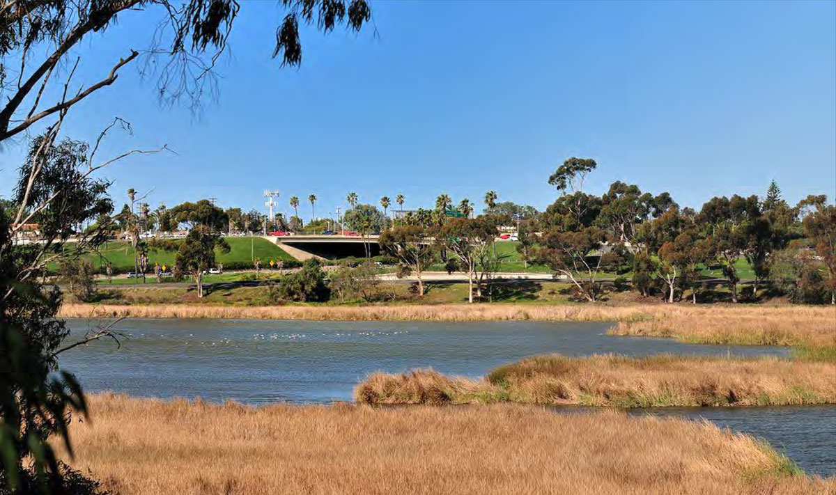
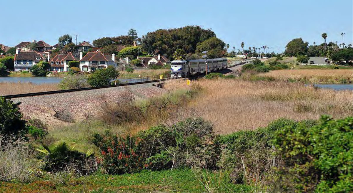
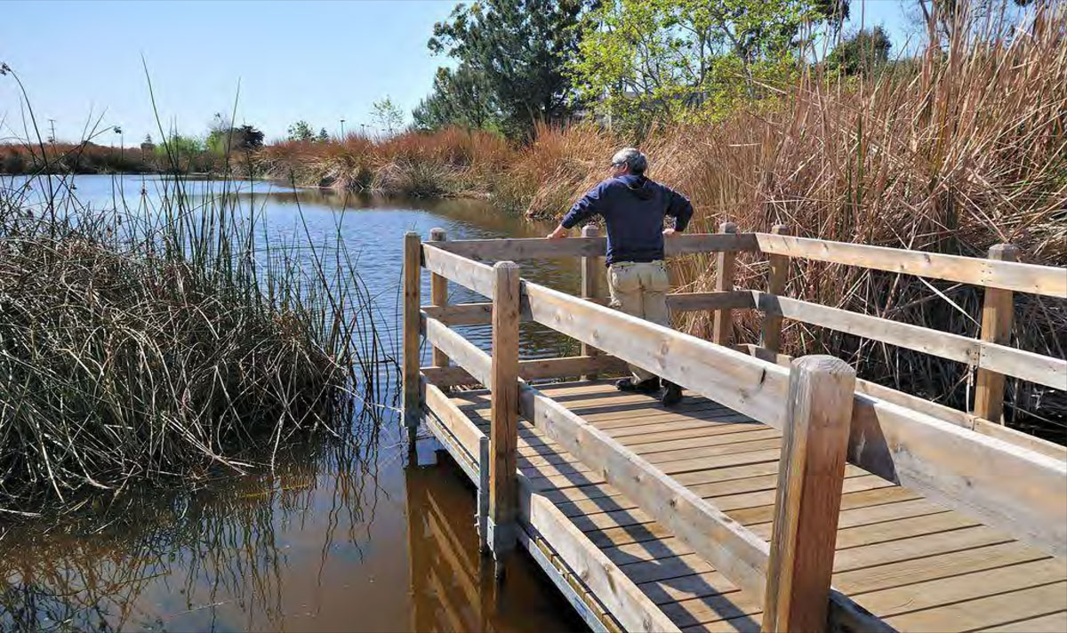
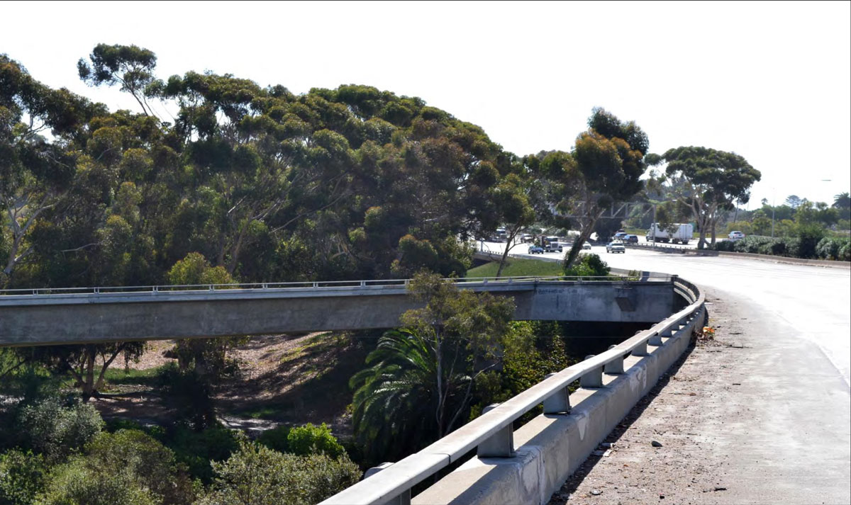
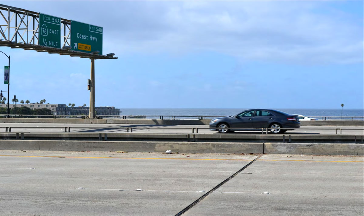
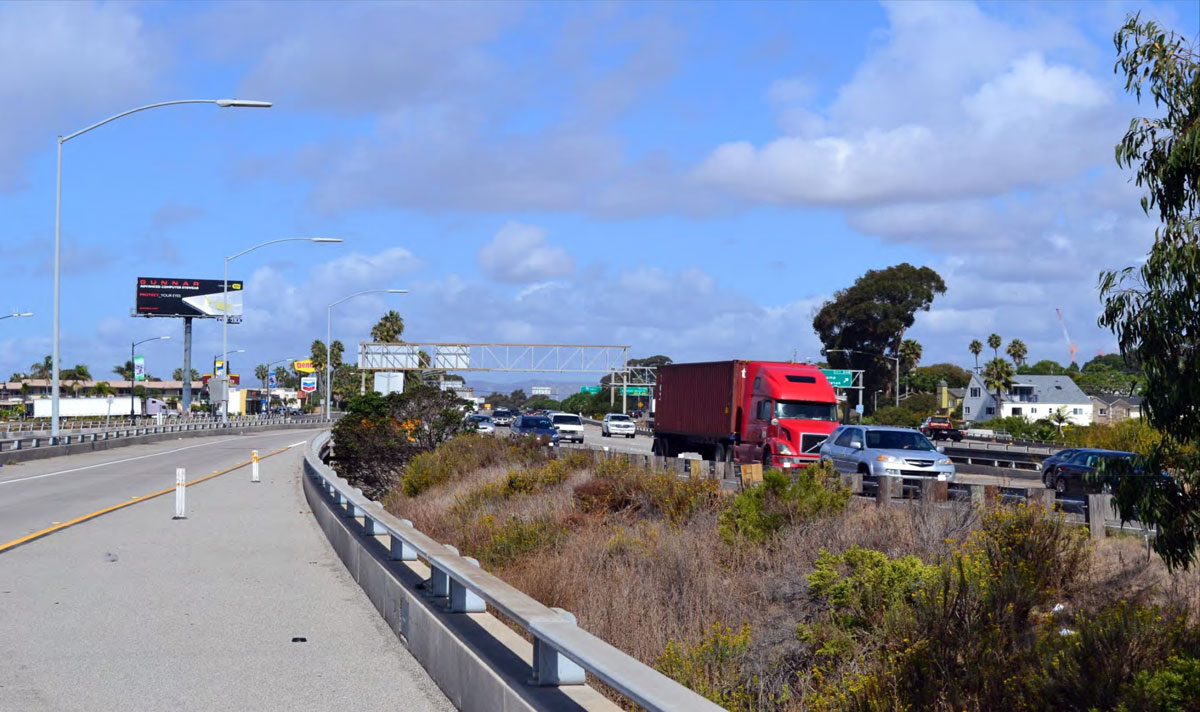
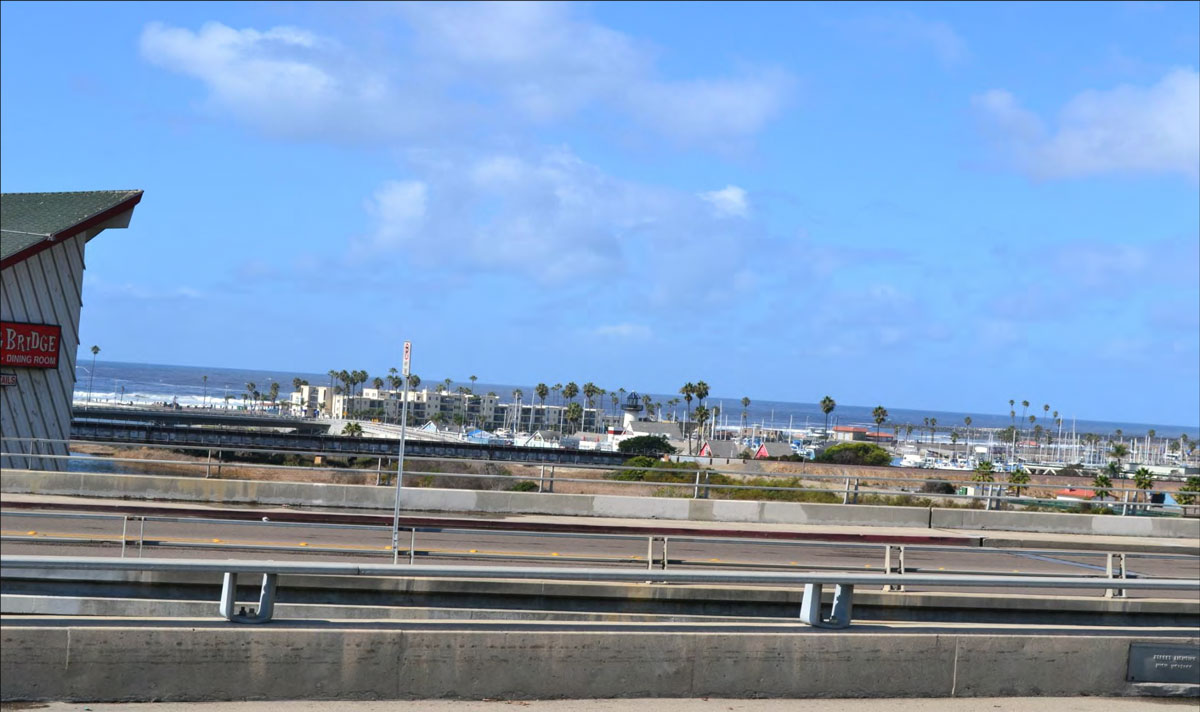
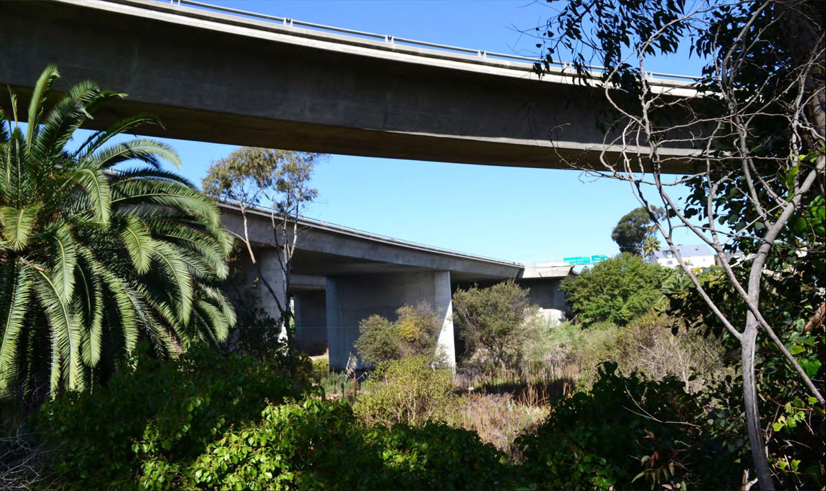
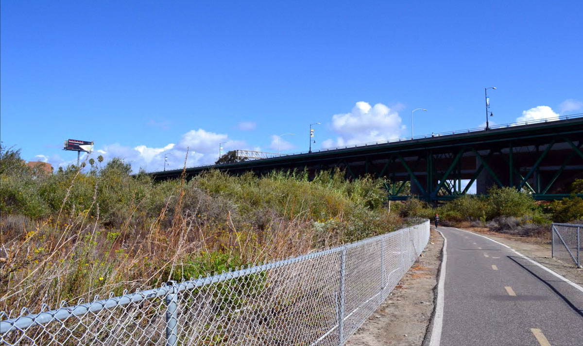
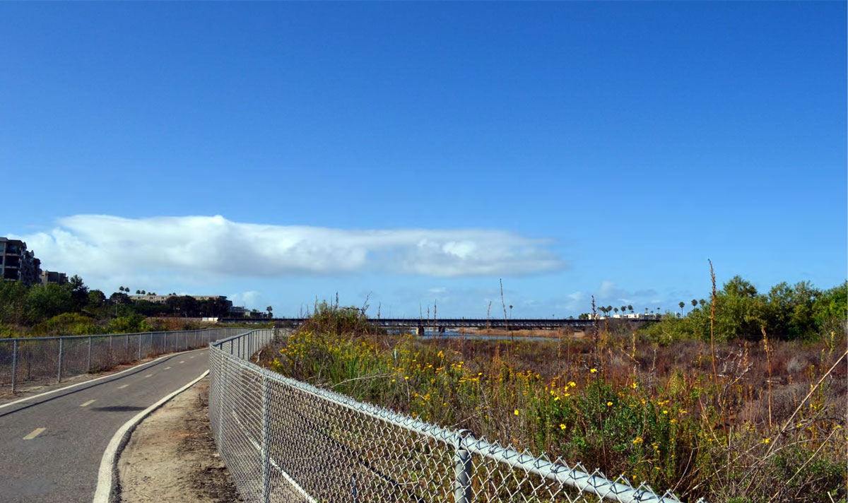
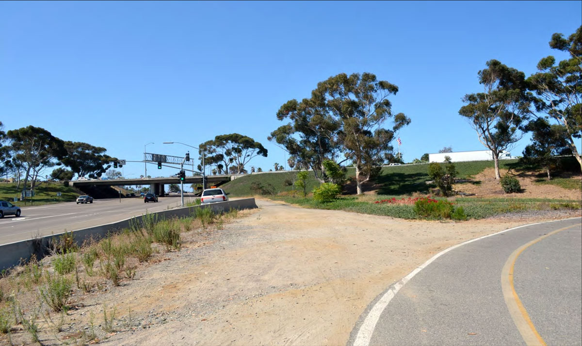
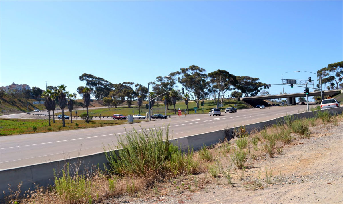
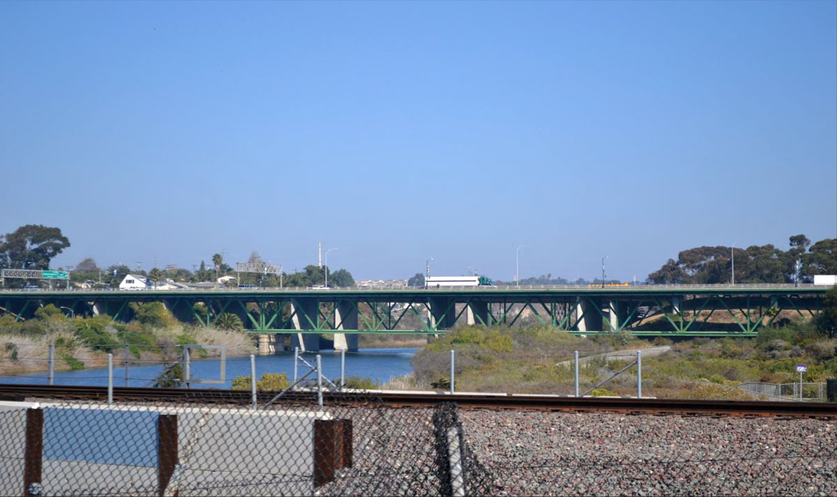
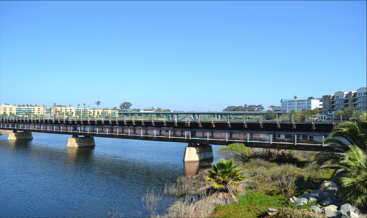
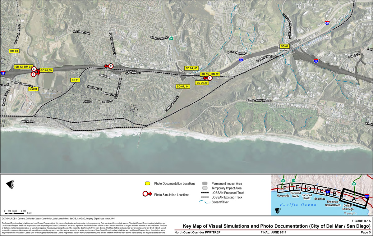
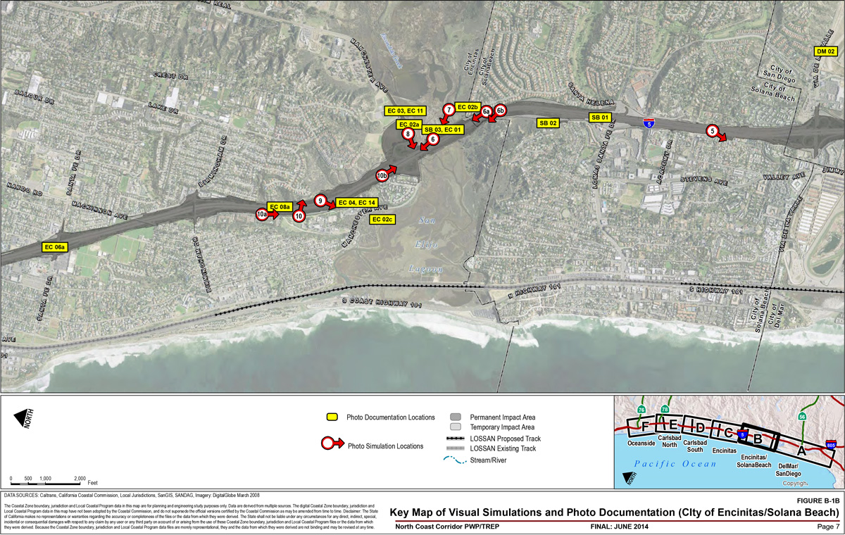
Photo Documentation: Current photographs of various locations along the Interstate 5 (I-5) highway corridor. Table B-1 lists the view locations and the number of photographs that appear for
each. Figures B-1A through B-1G are key maps illustrating the locations of
each view. The photographs themselves appear on the gallery after the maps, and are lettered sequentially
based on their view number (e.g. Figure SD-01A, Figure SD-01B, etc.).
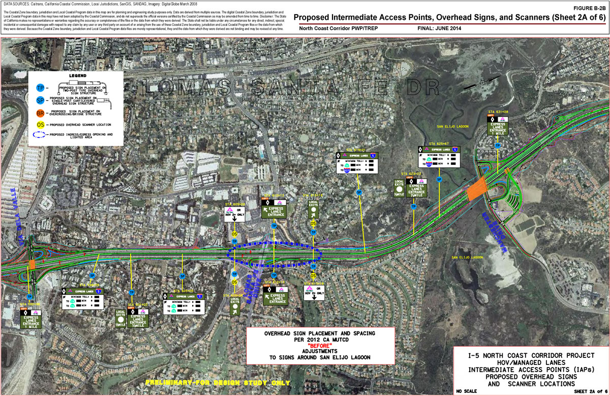
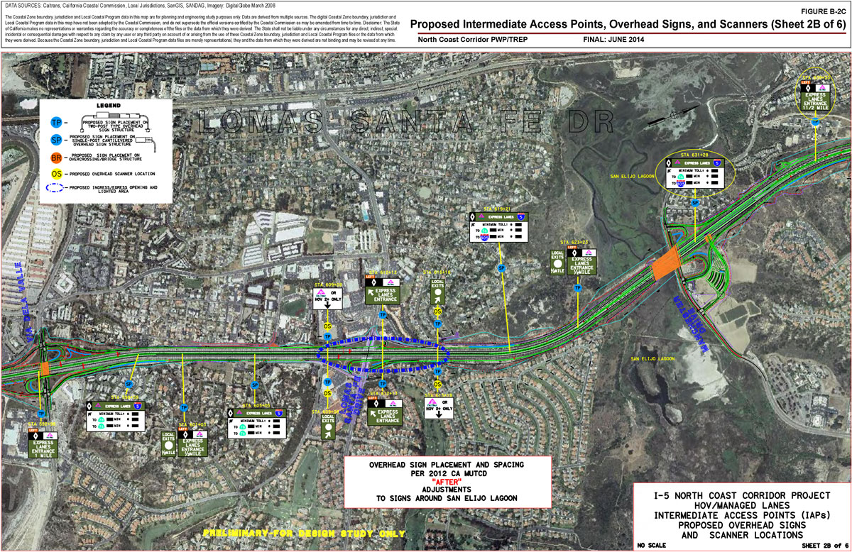
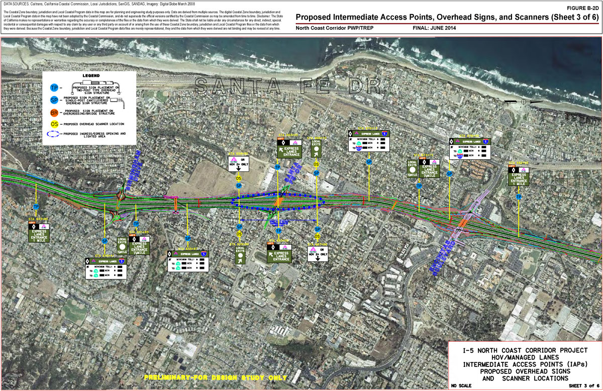
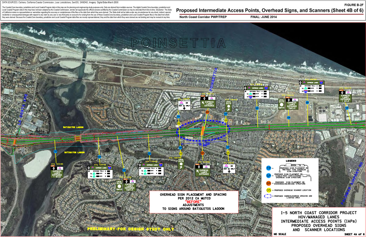
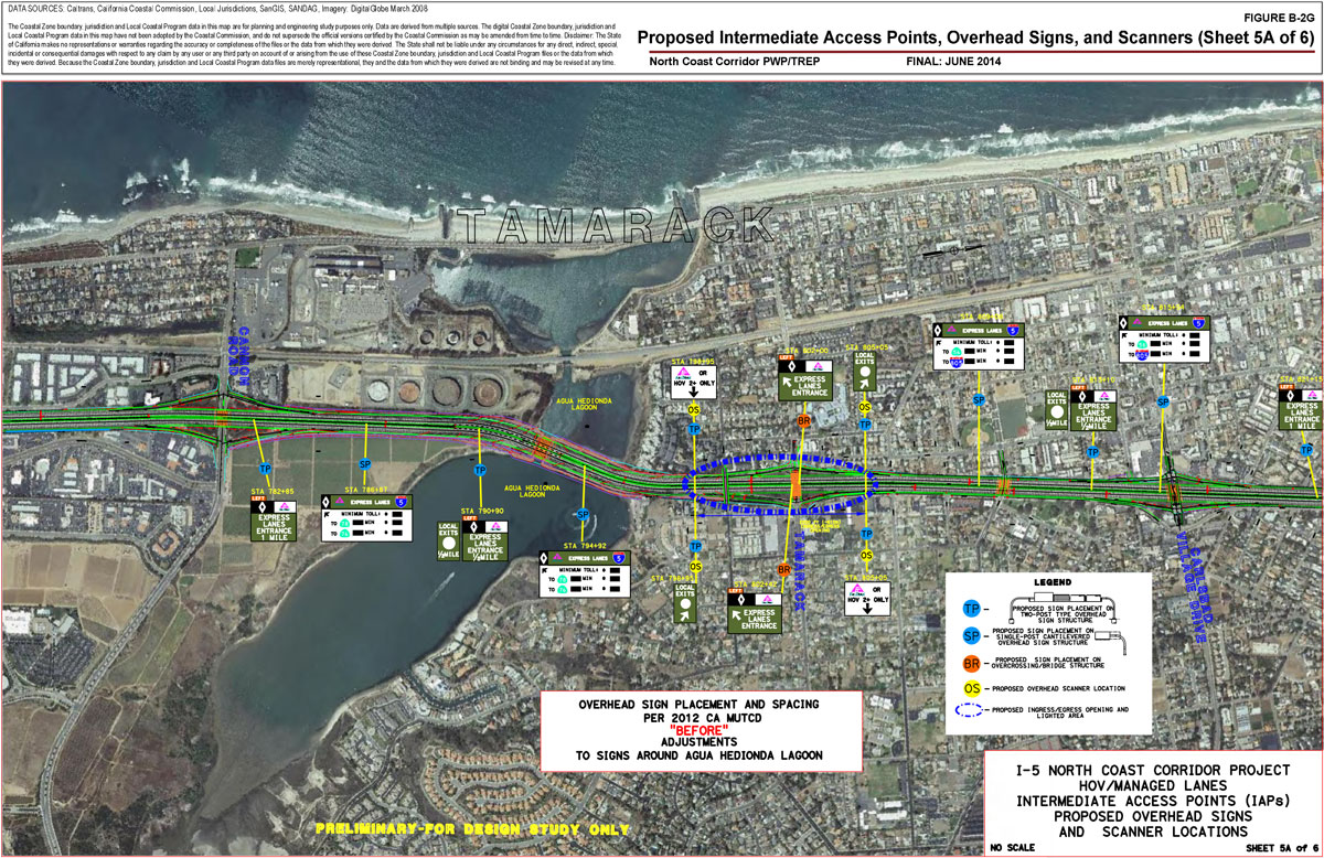
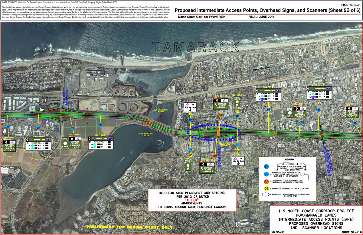
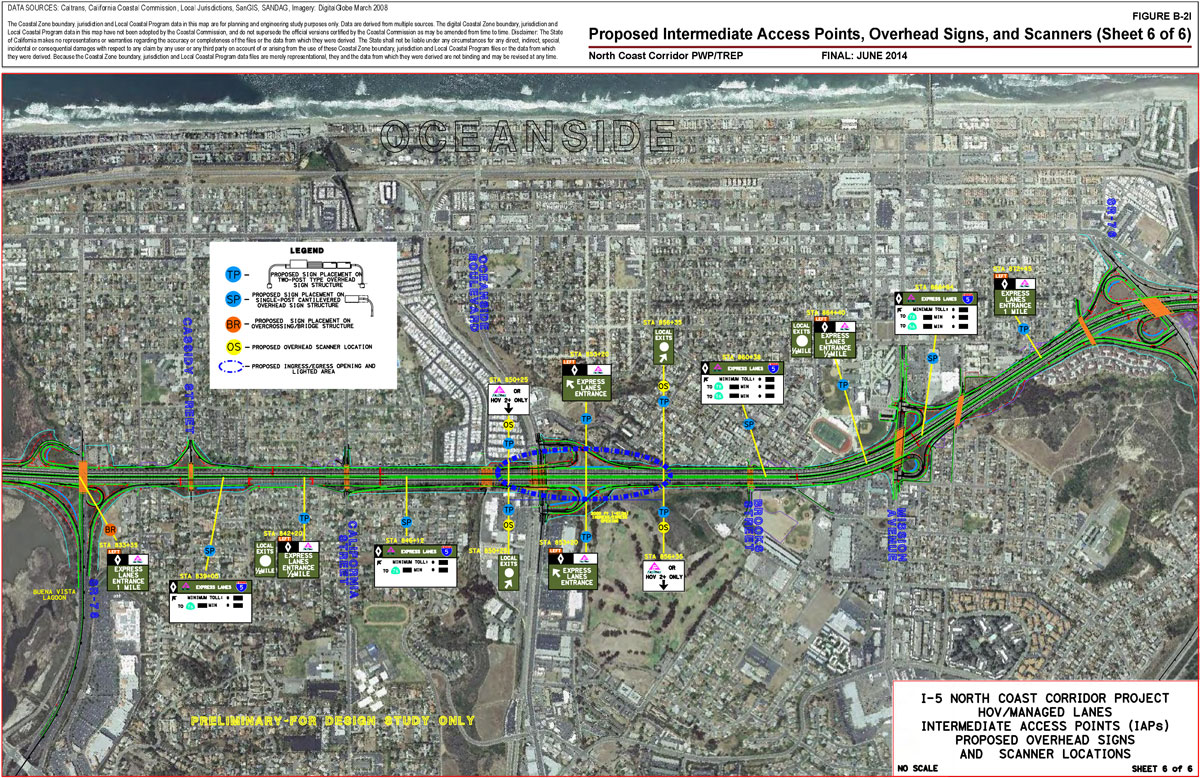
Proposed Locations of Intermediate Access Points (IAPs), Overhead Signs and Scanners: At the start of the gallery, Figures B-2A through B-2I are maps of proposed locations for Express
Lane IAPs, overhead signs and overhead scanners.
IAP Signage Criteria: The final section of this appendix contains
descriptions, schematics and photos of proposed design features for corridor signs at IAP
locations.
Table B-1: Photo Documentation View Locations
Data sources: Google, Caltrans.
View No.
View Description
No. of Images
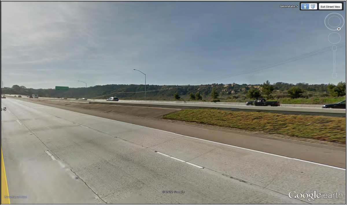
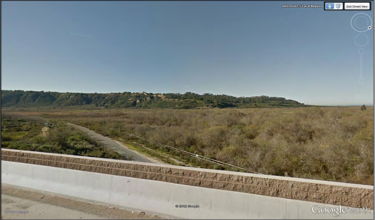
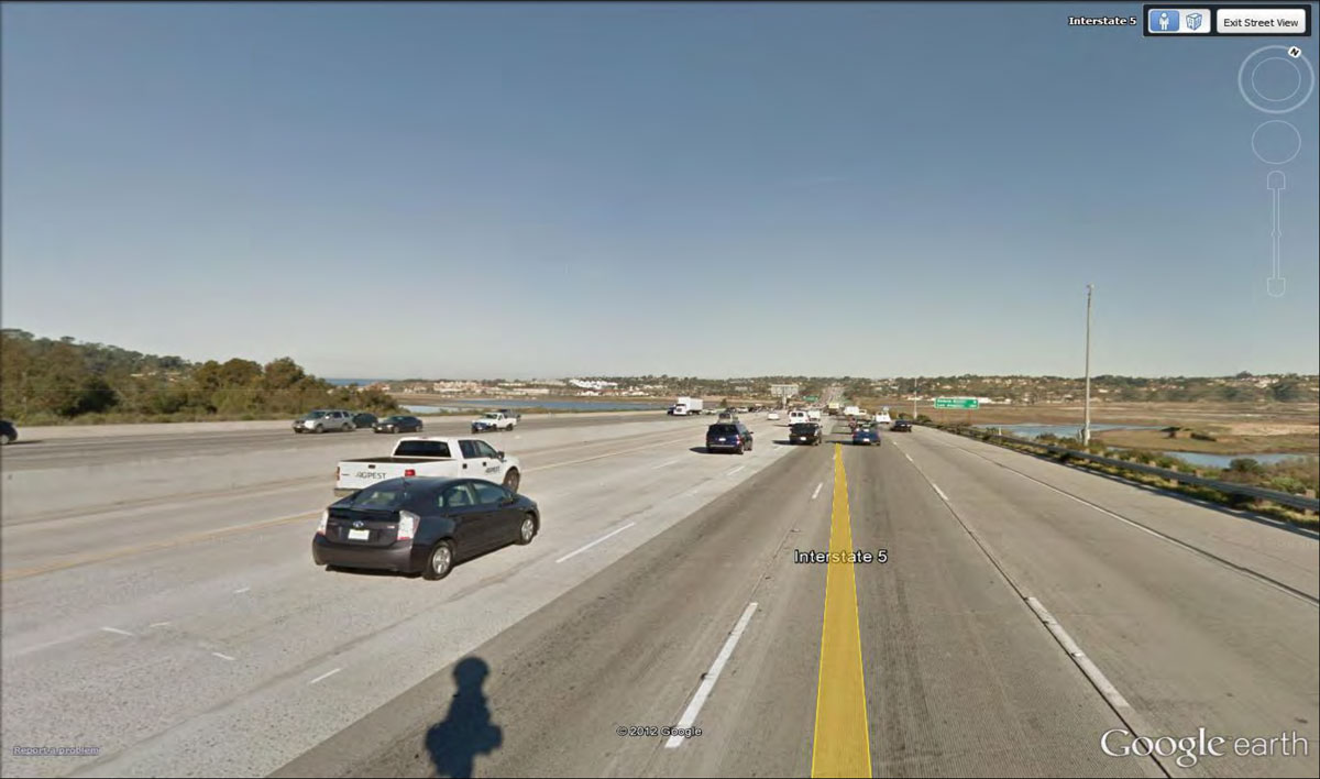
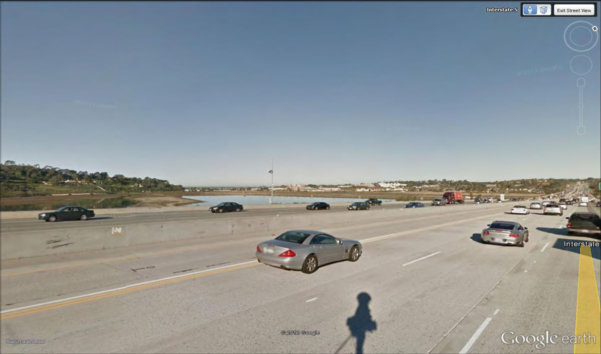
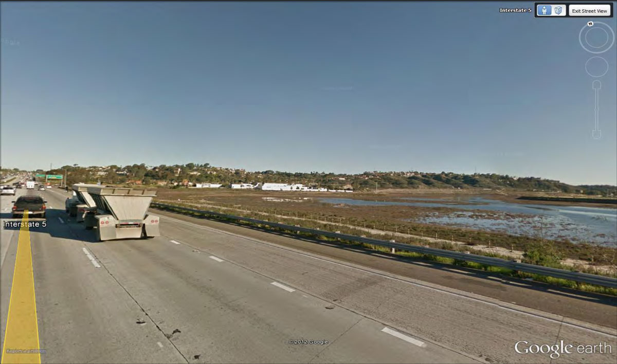
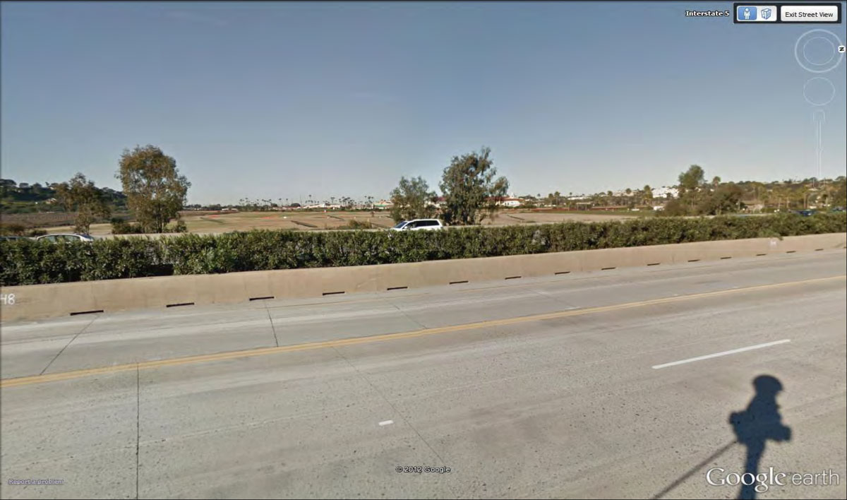
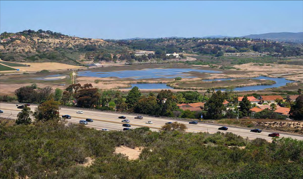
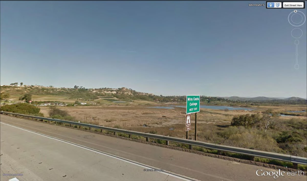
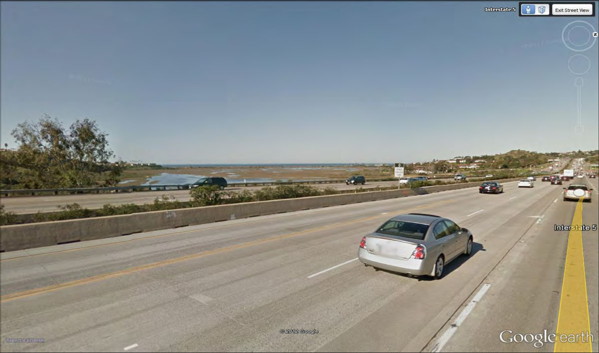
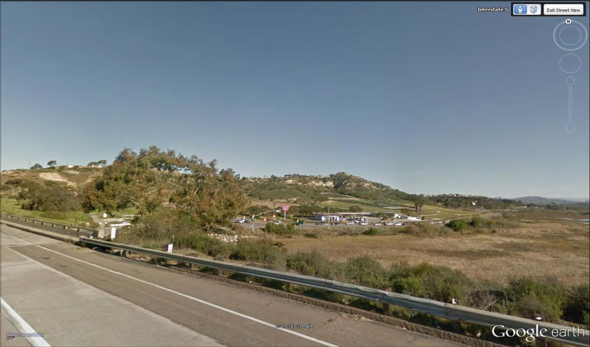
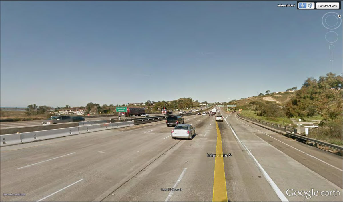
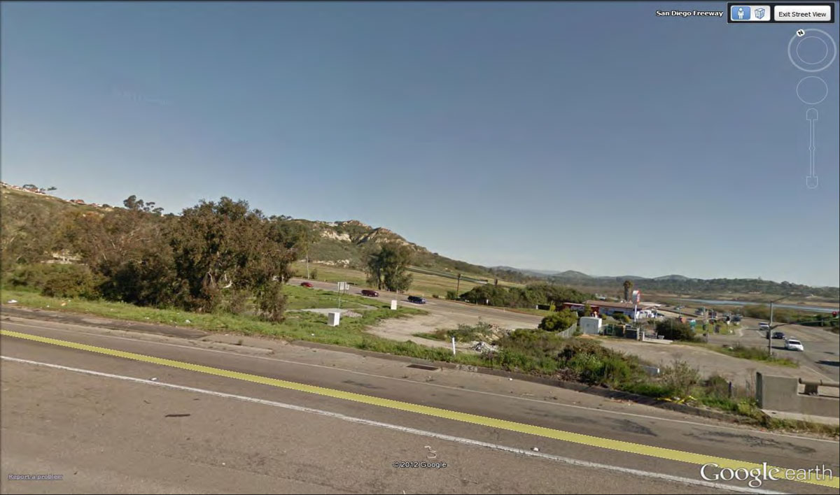
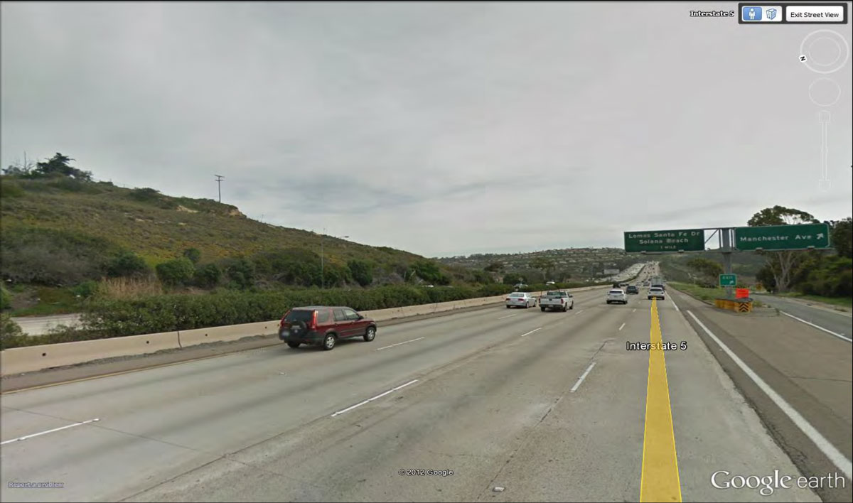
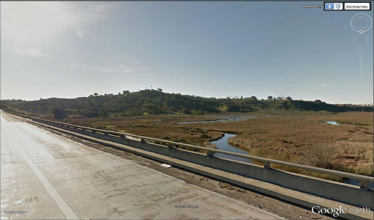
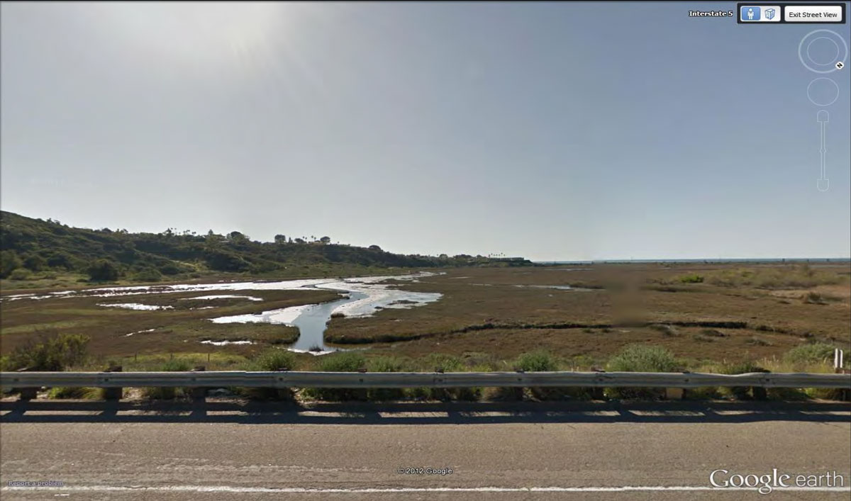
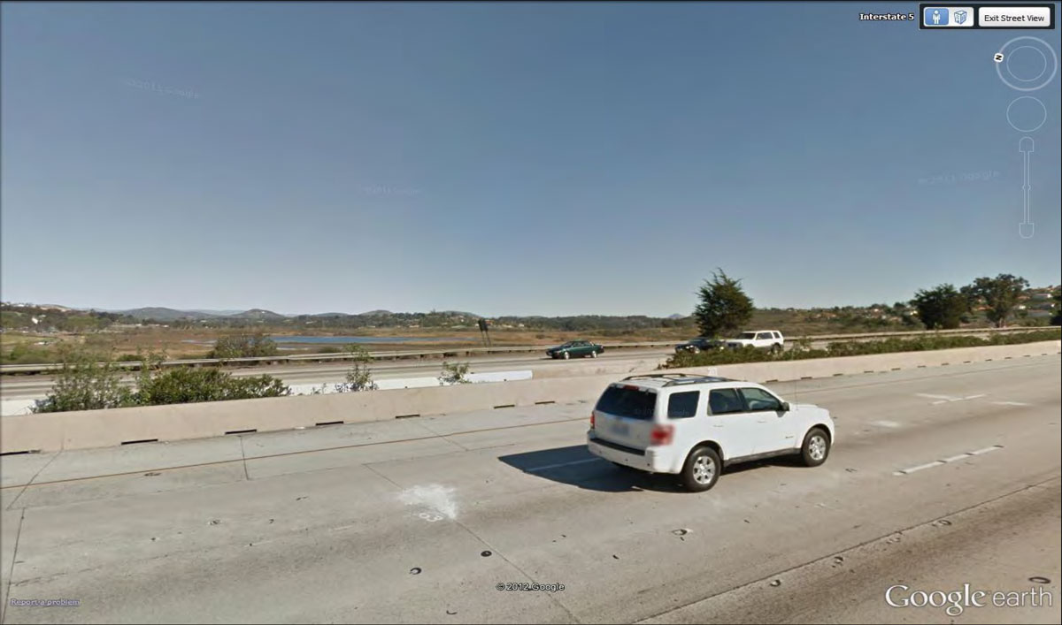
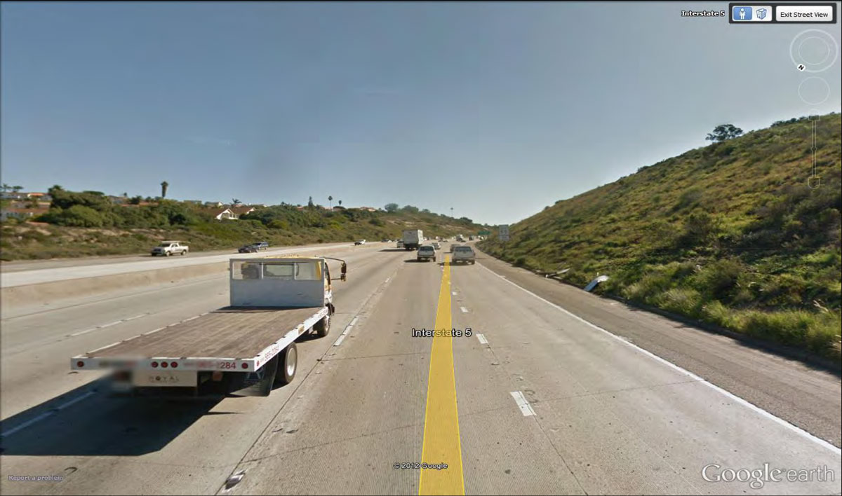
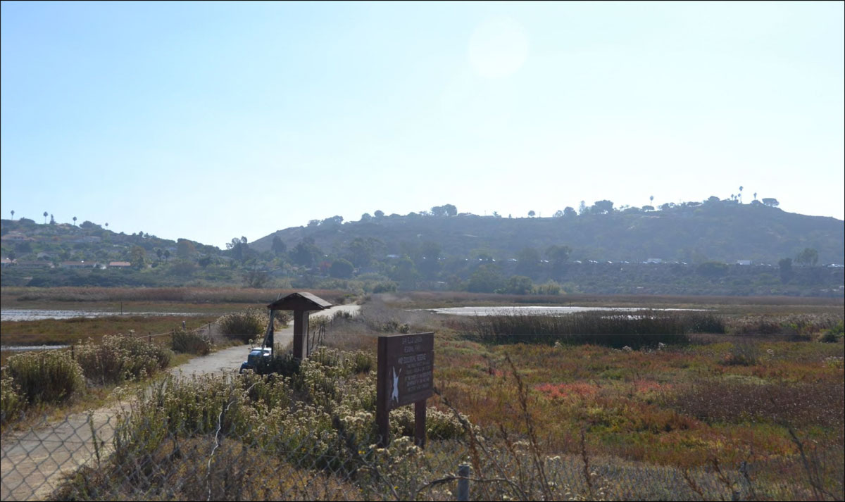
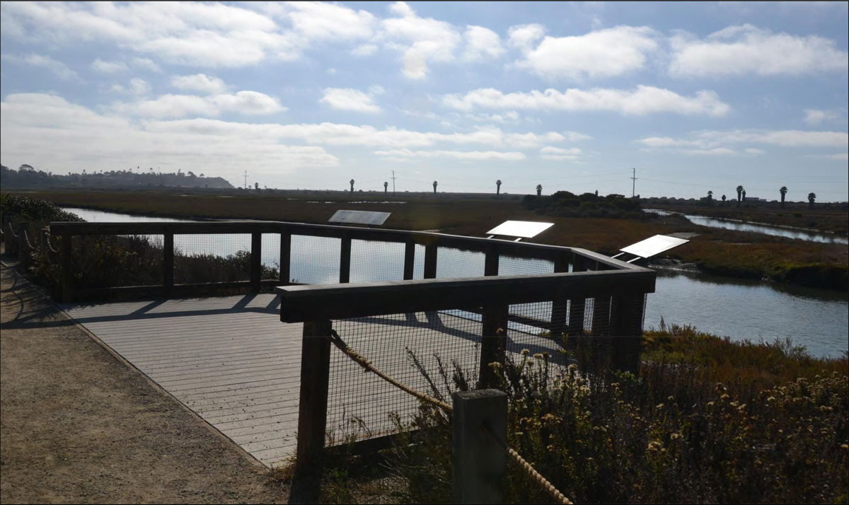
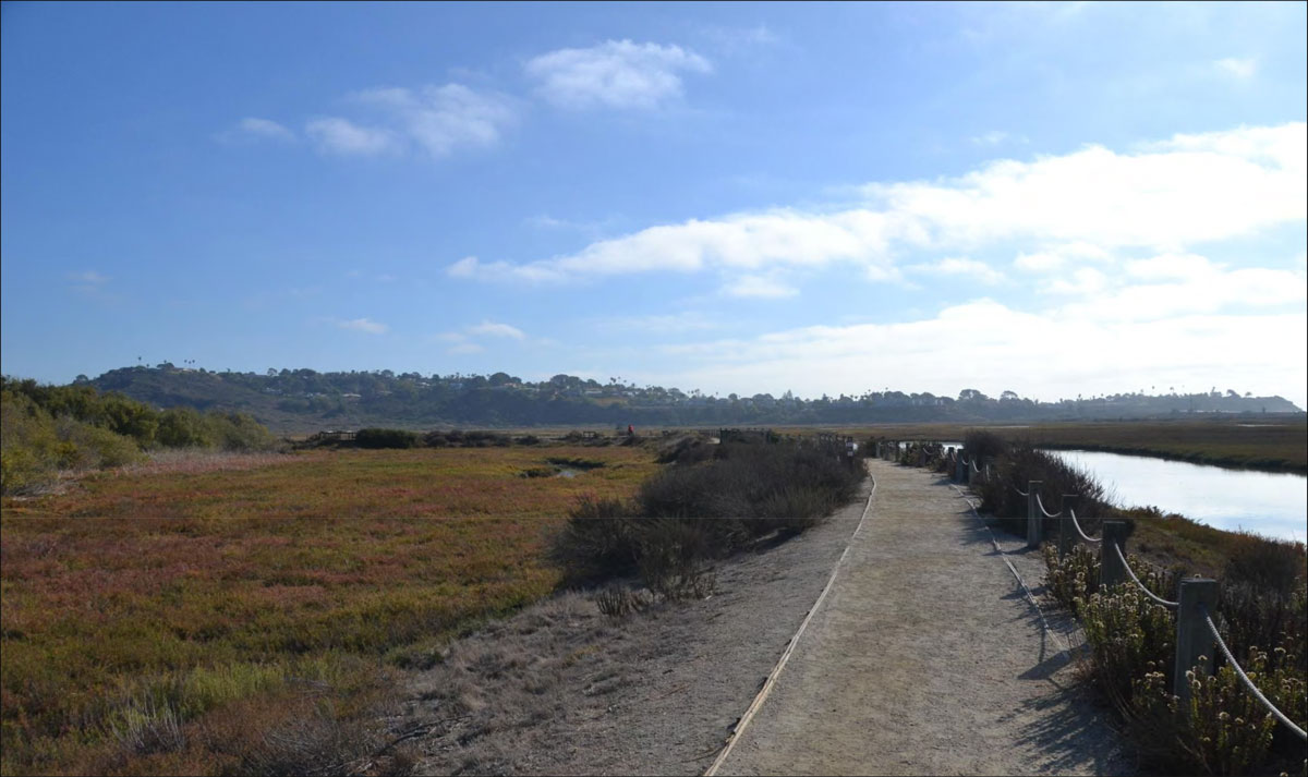
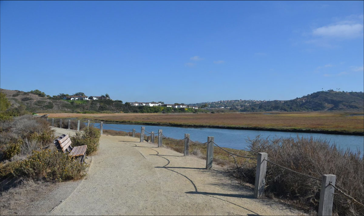
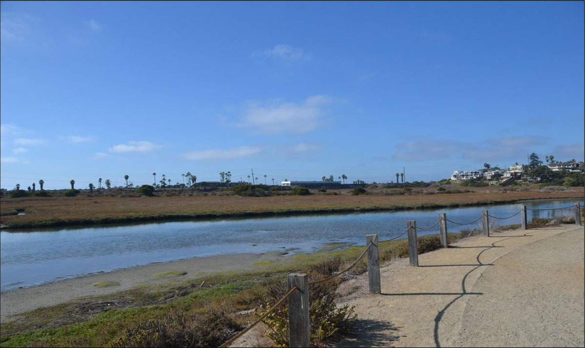
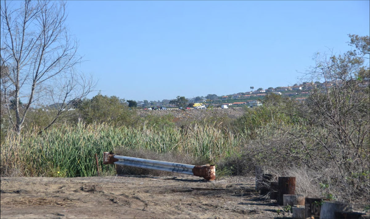
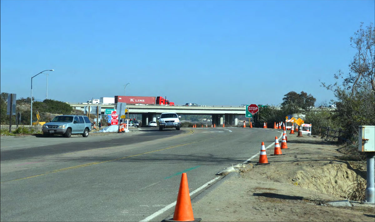
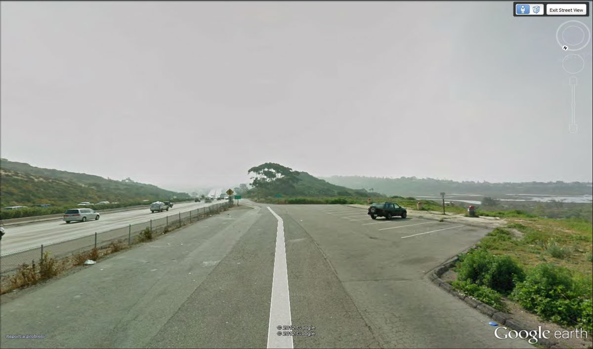
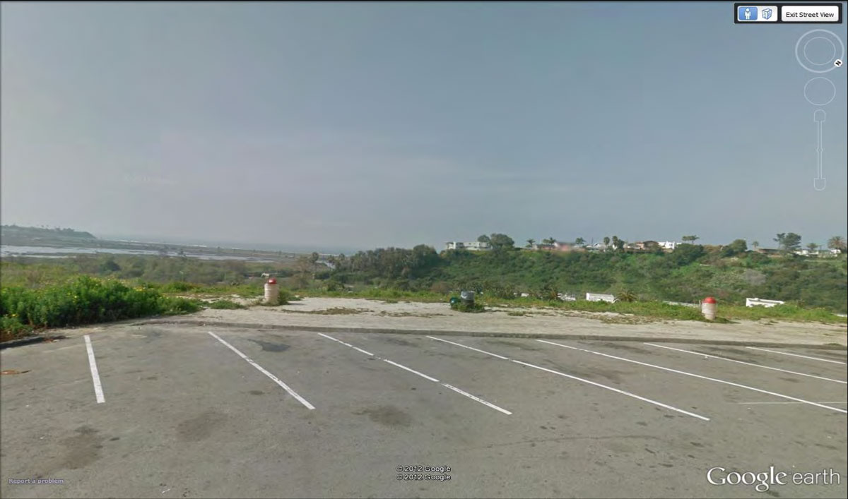
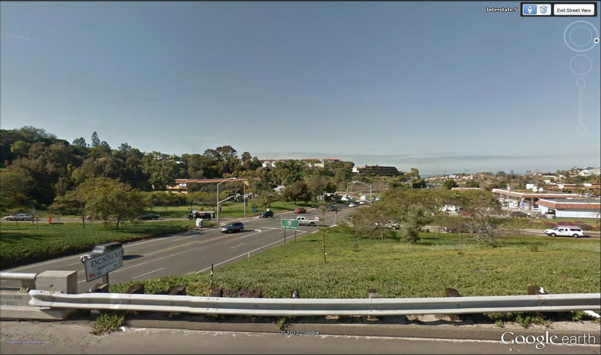
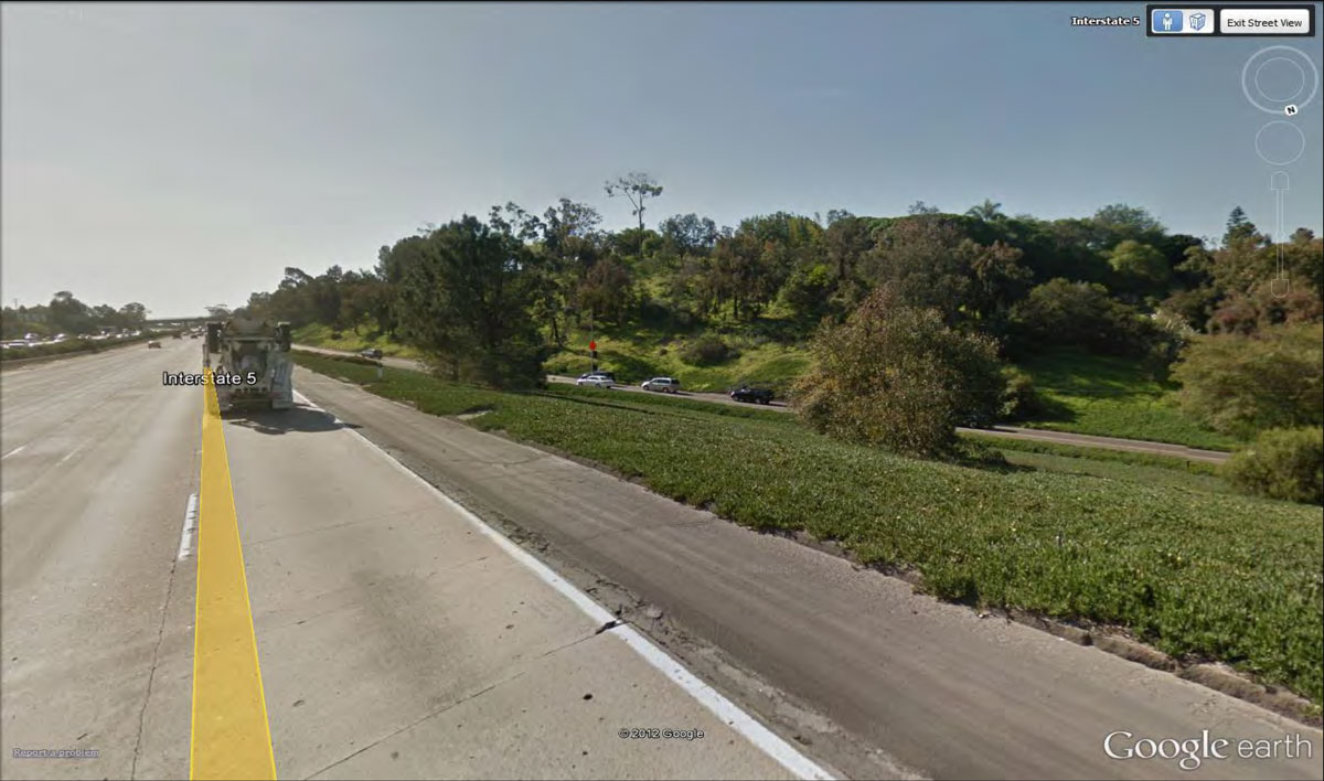
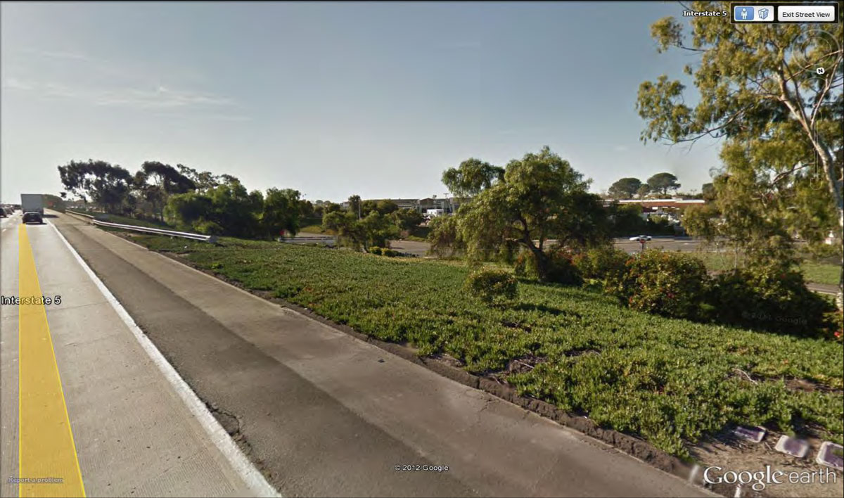
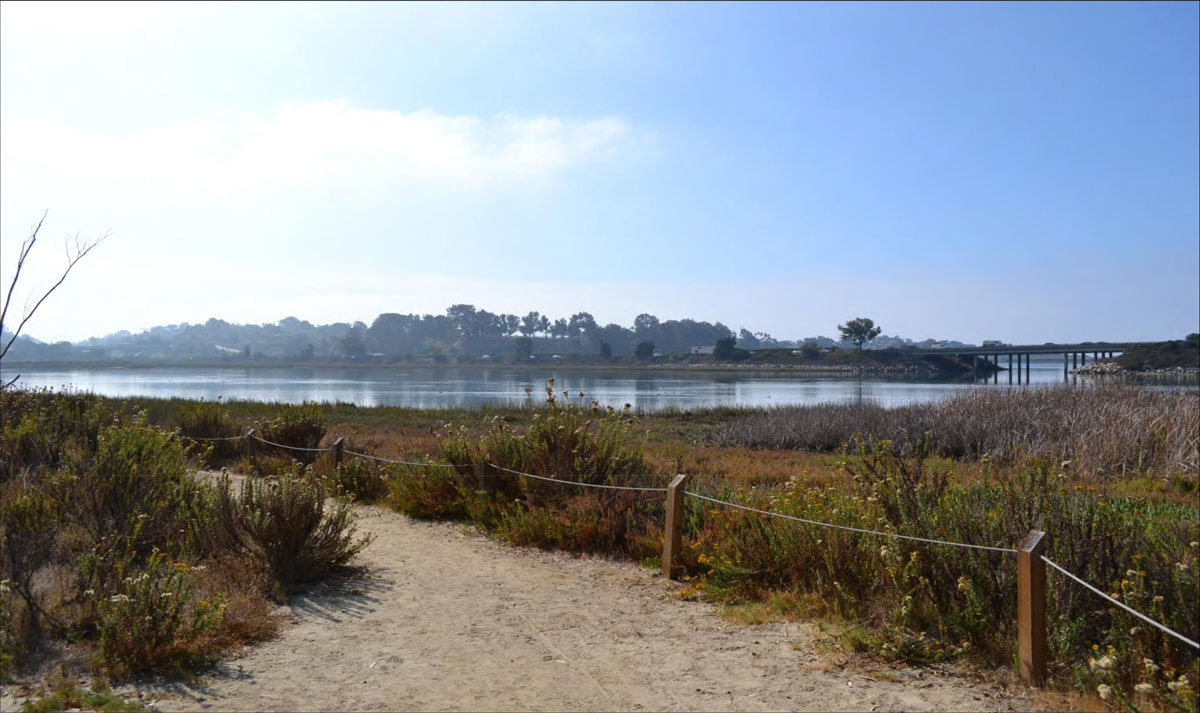
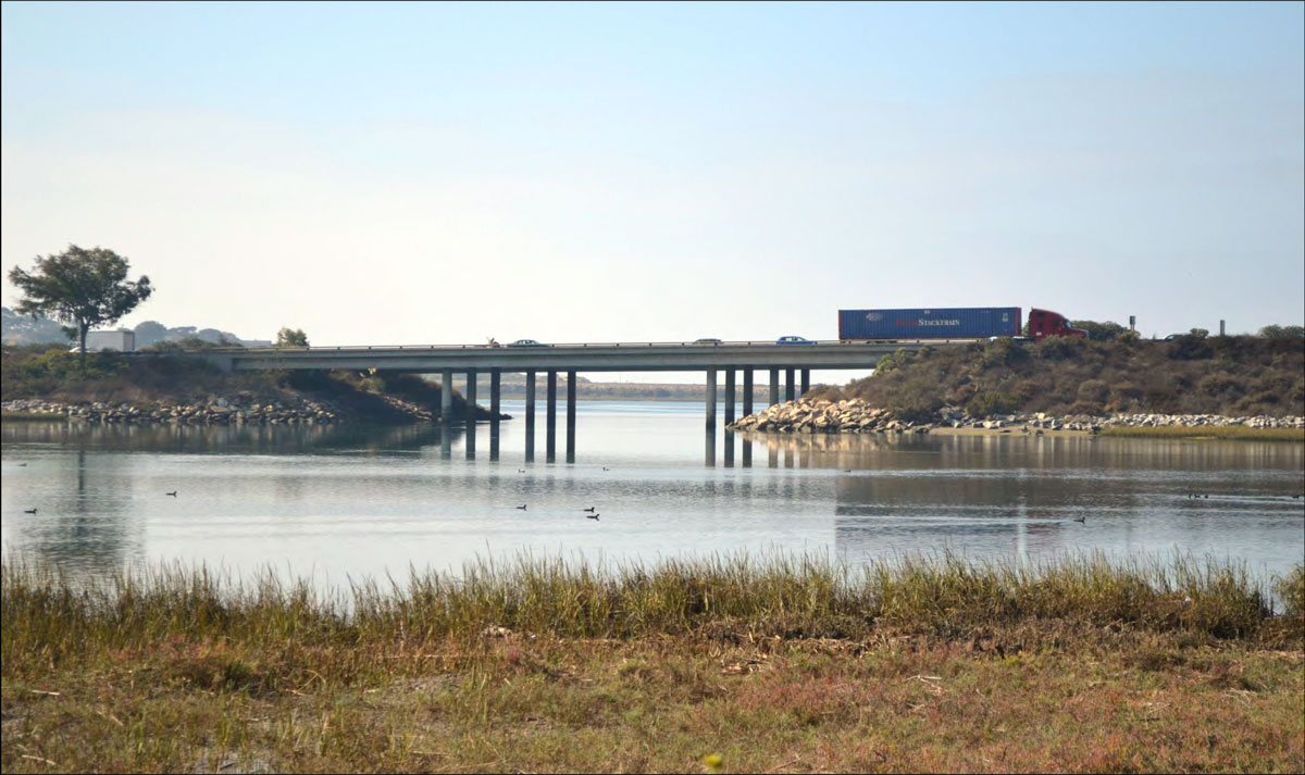
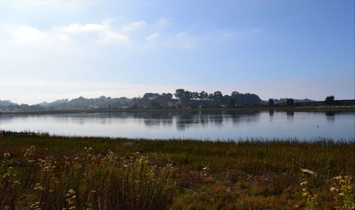
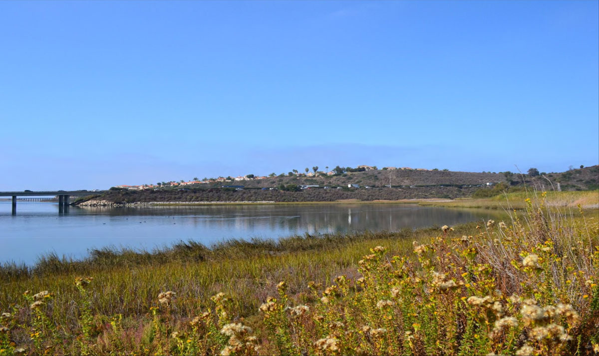
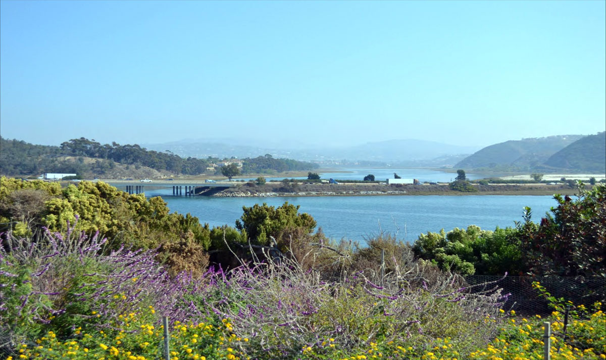
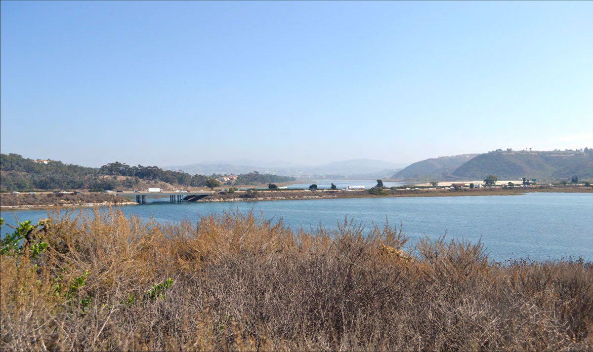
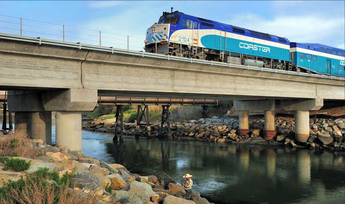
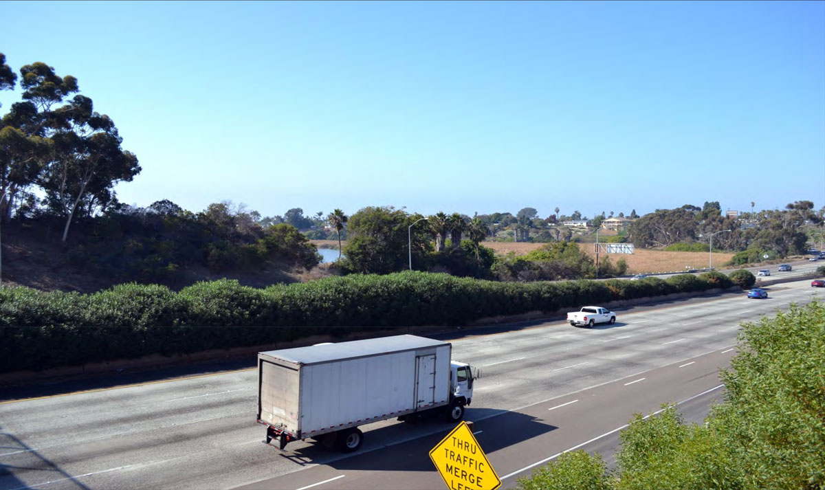
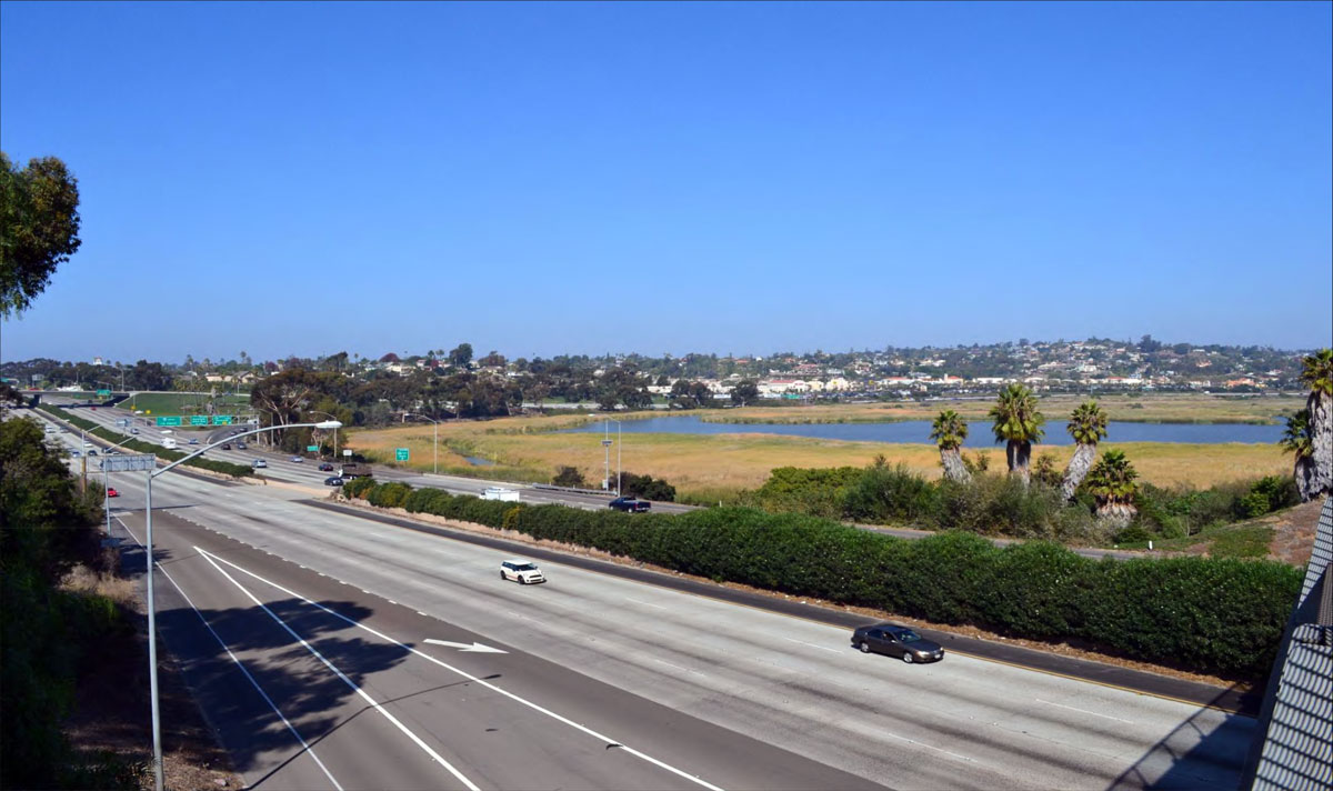
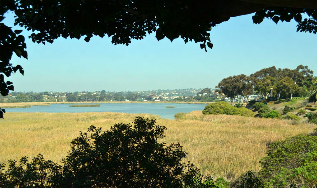
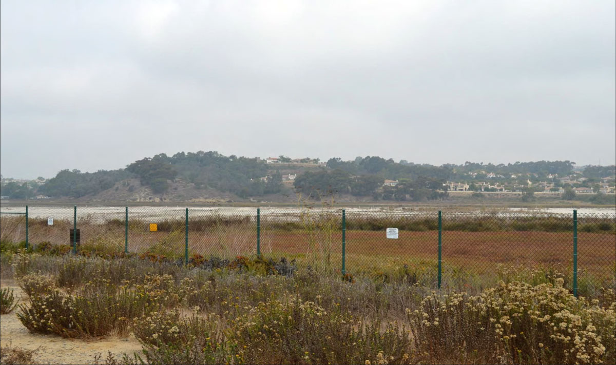
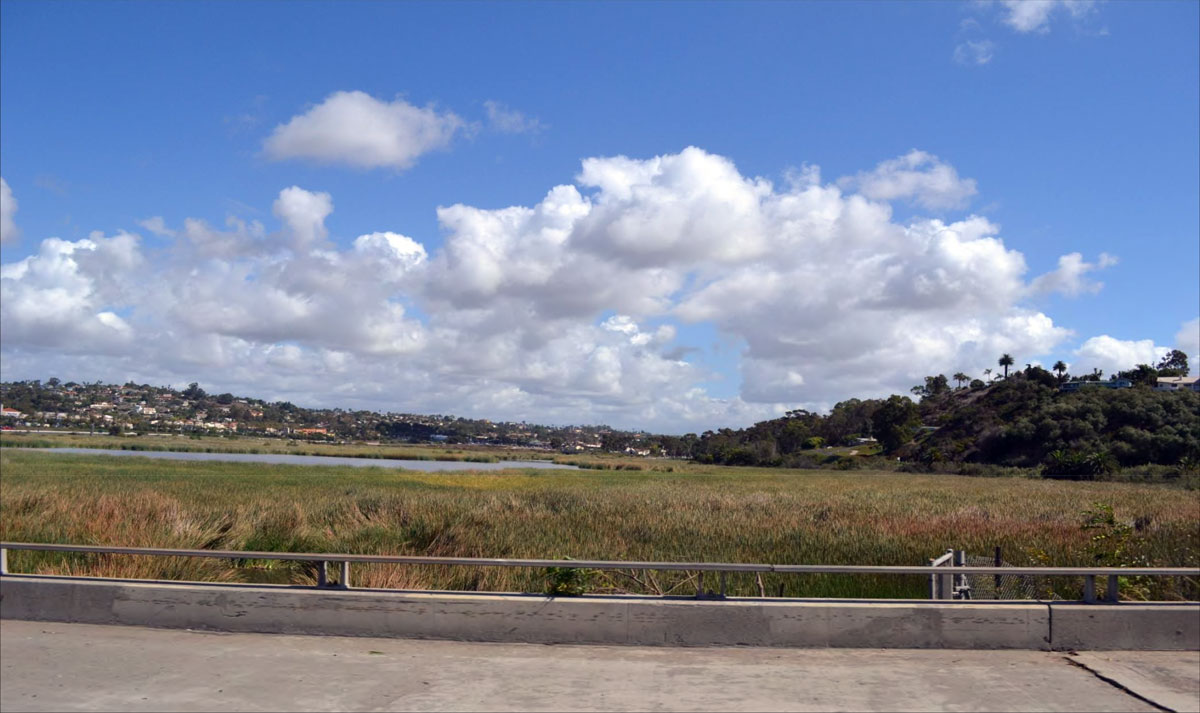
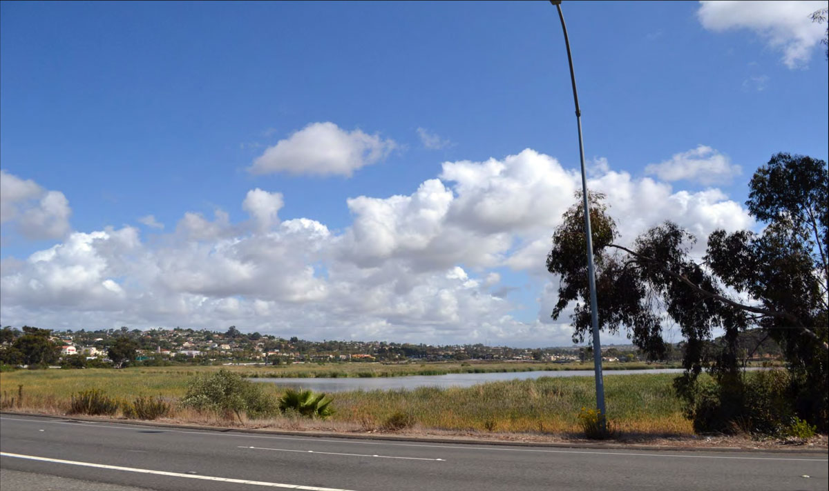
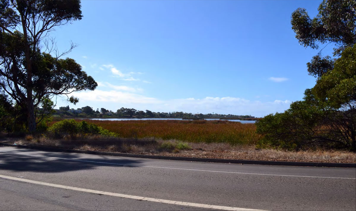
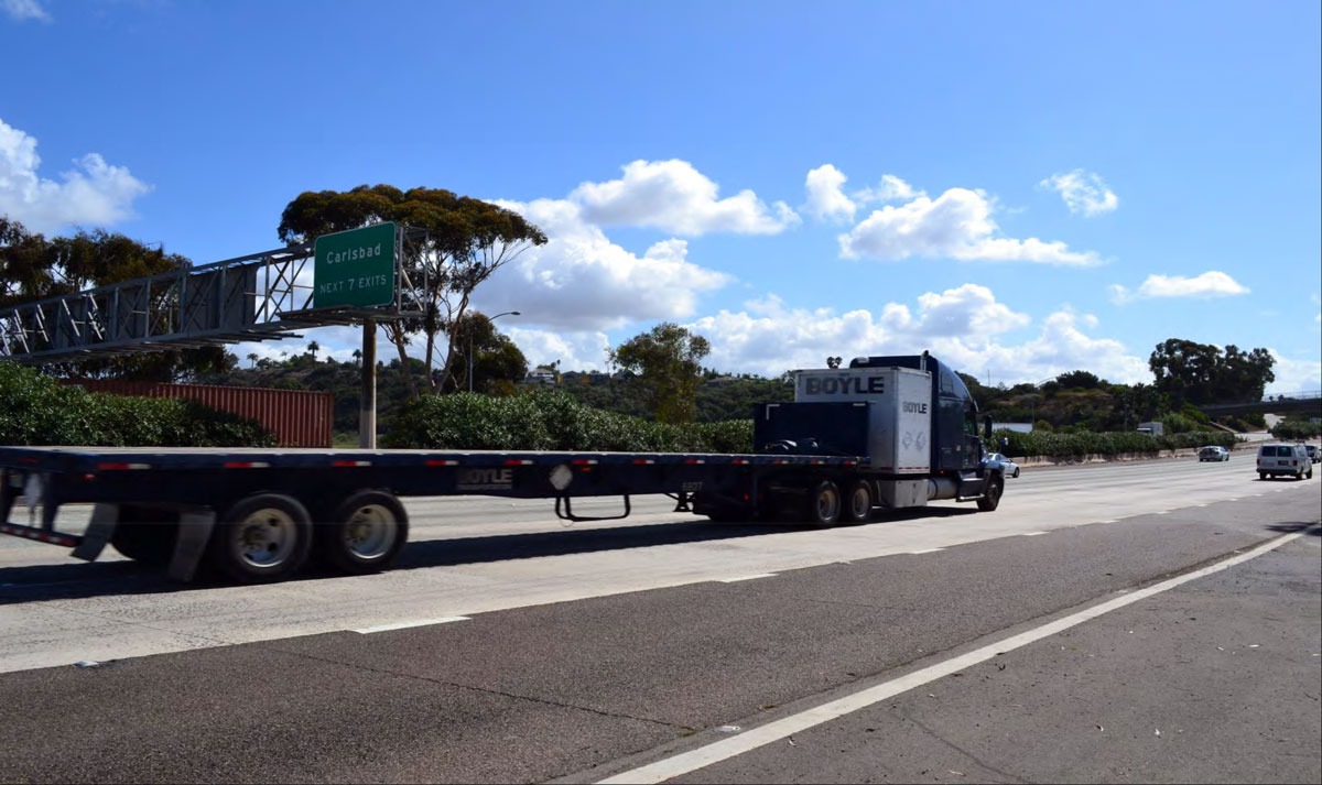
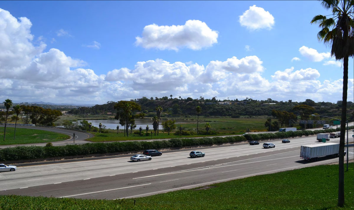
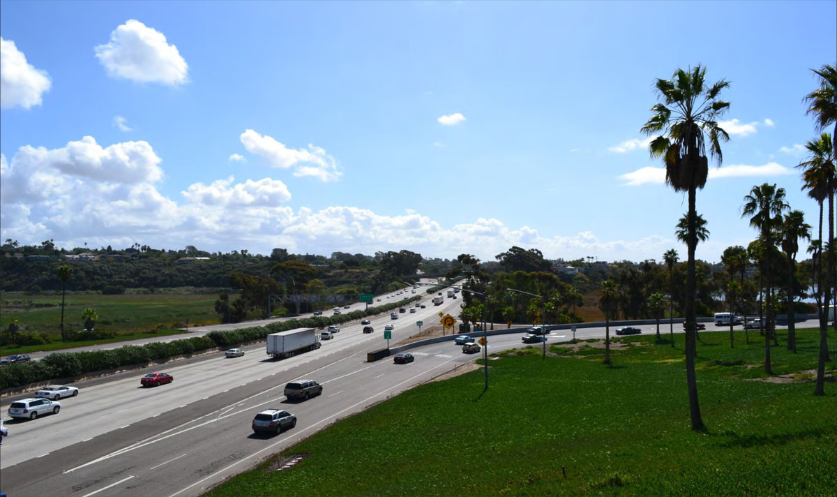
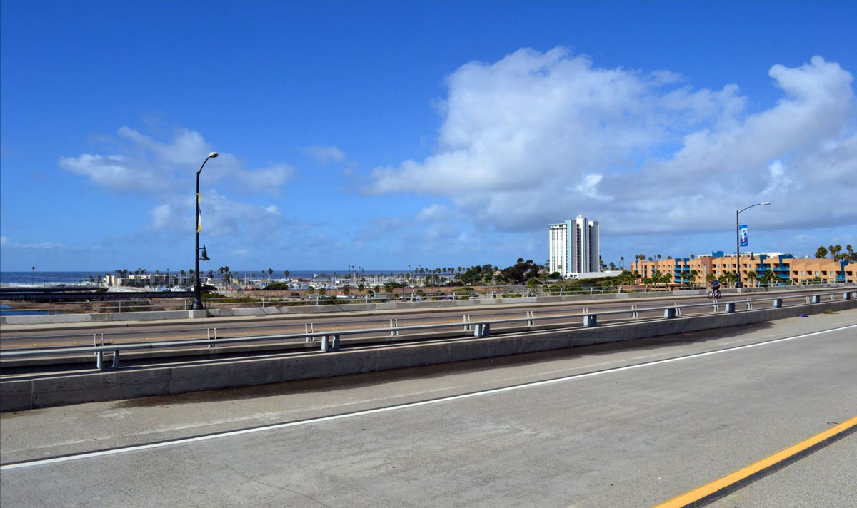
City of Solana Beach: San Dieguito Lagoon
SB-01
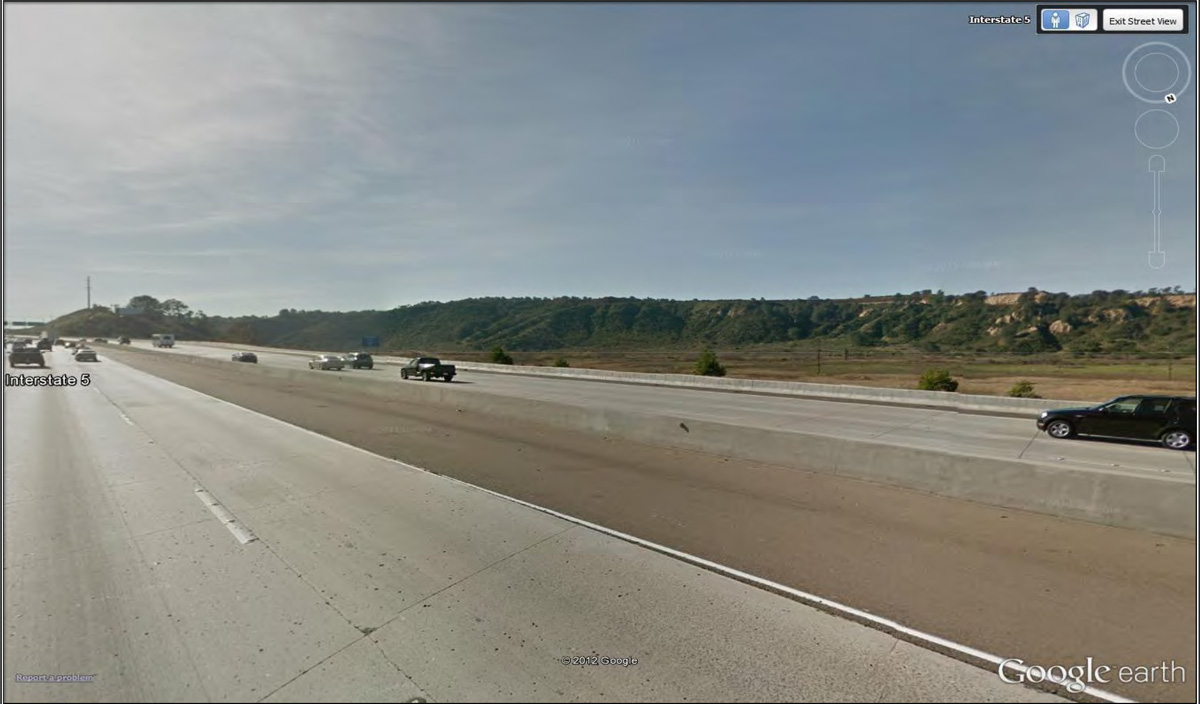
Western/Eastern Views from I-5 Including the Pacific Ocean, San Dieguito Lagoon, and Coastal and Inland Natural Coastal Landforms
17
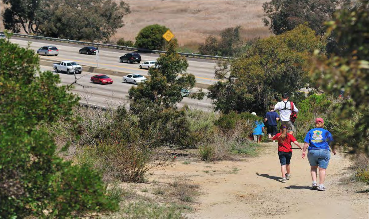
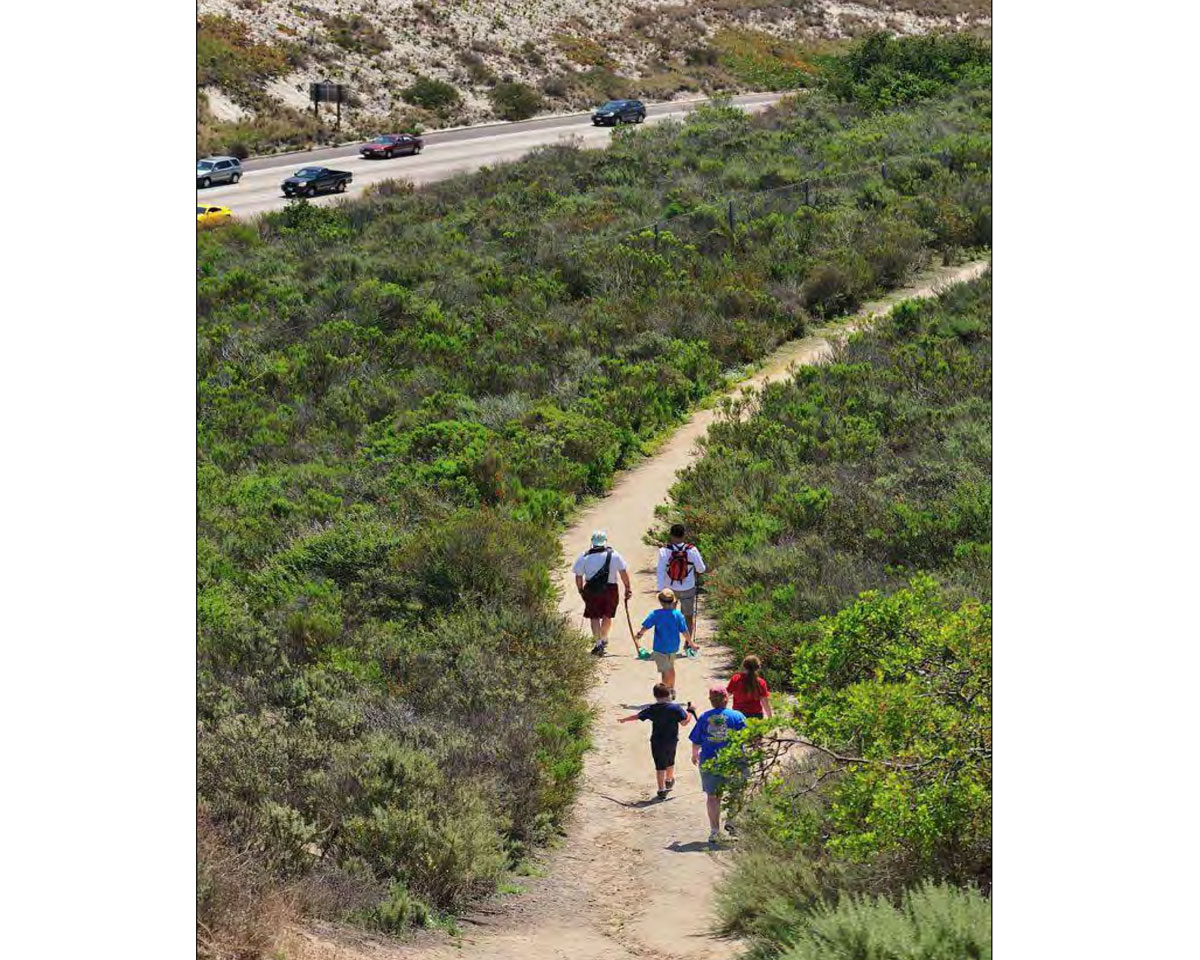
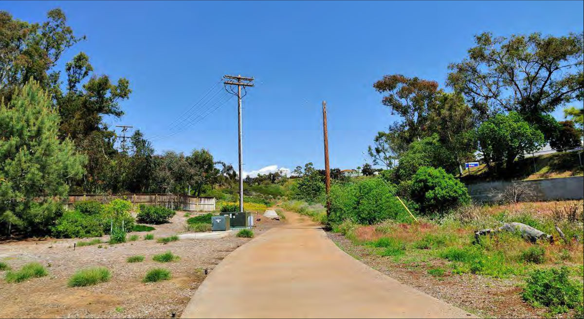
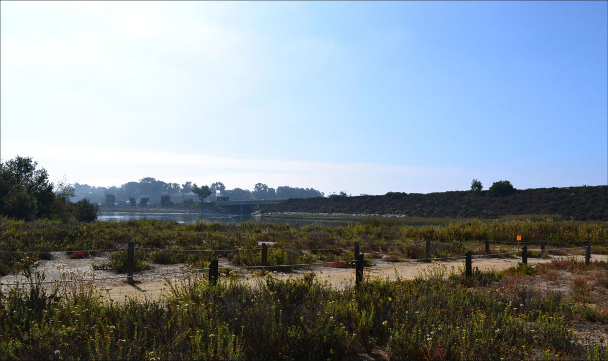
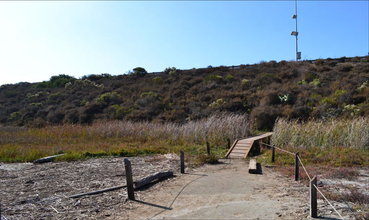
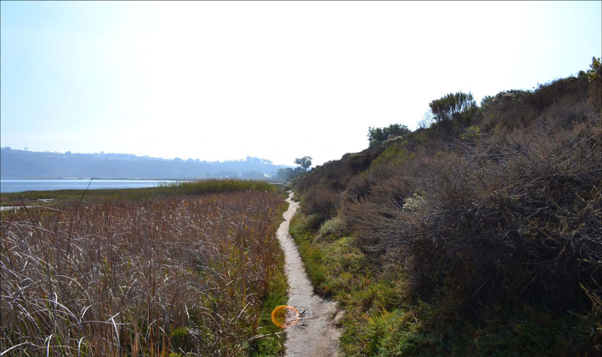
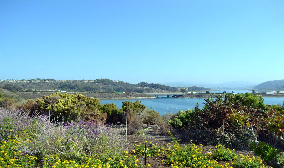
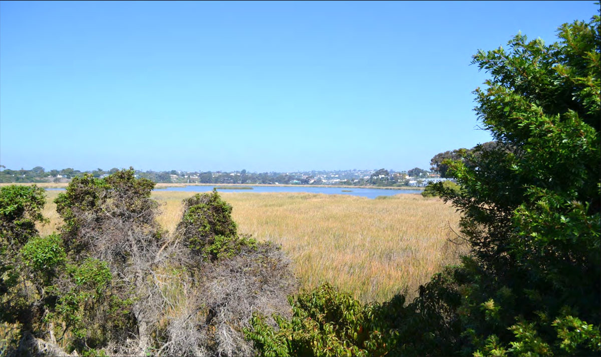
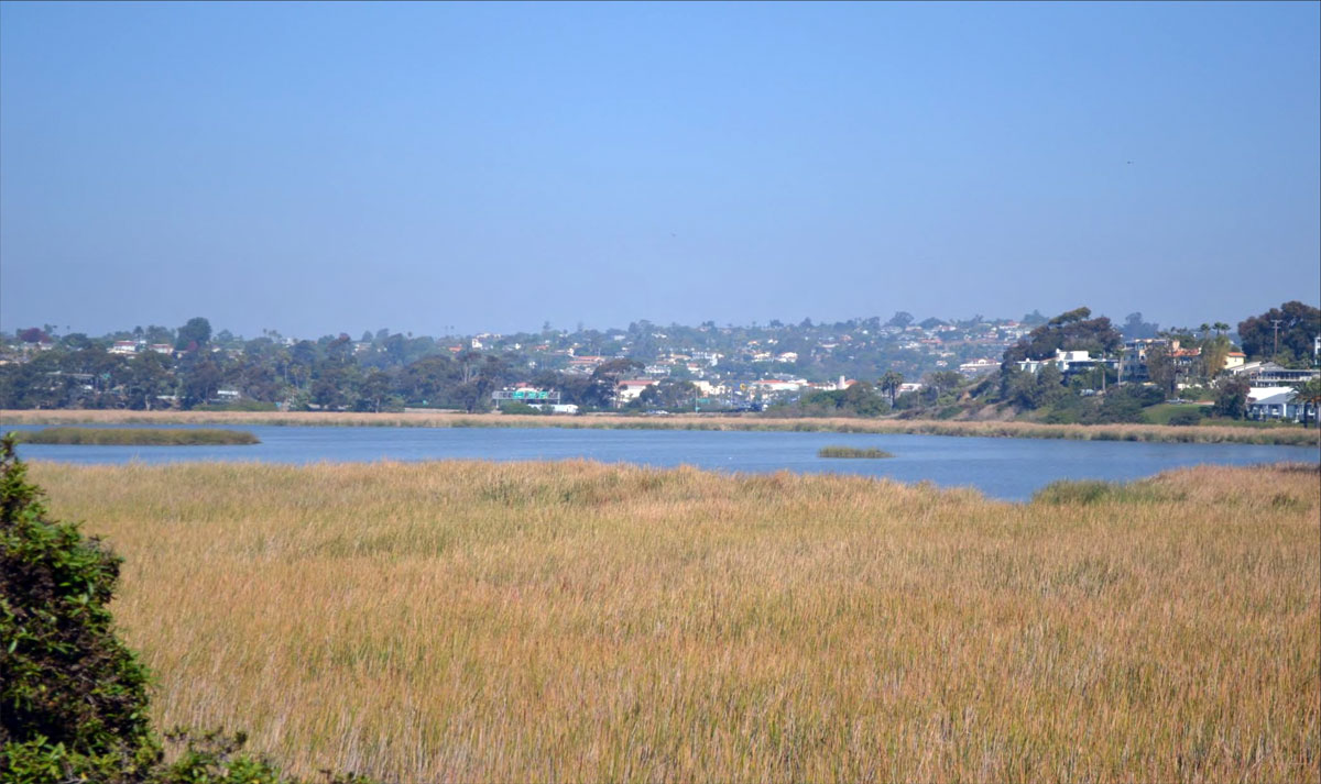
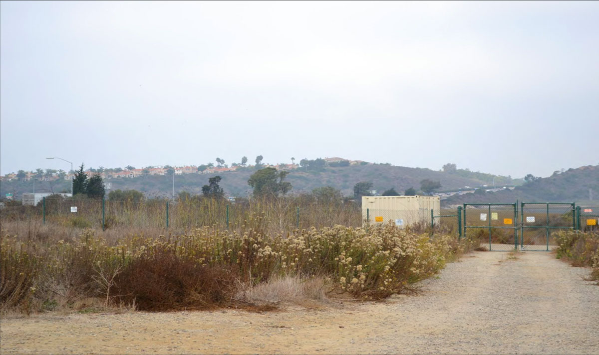
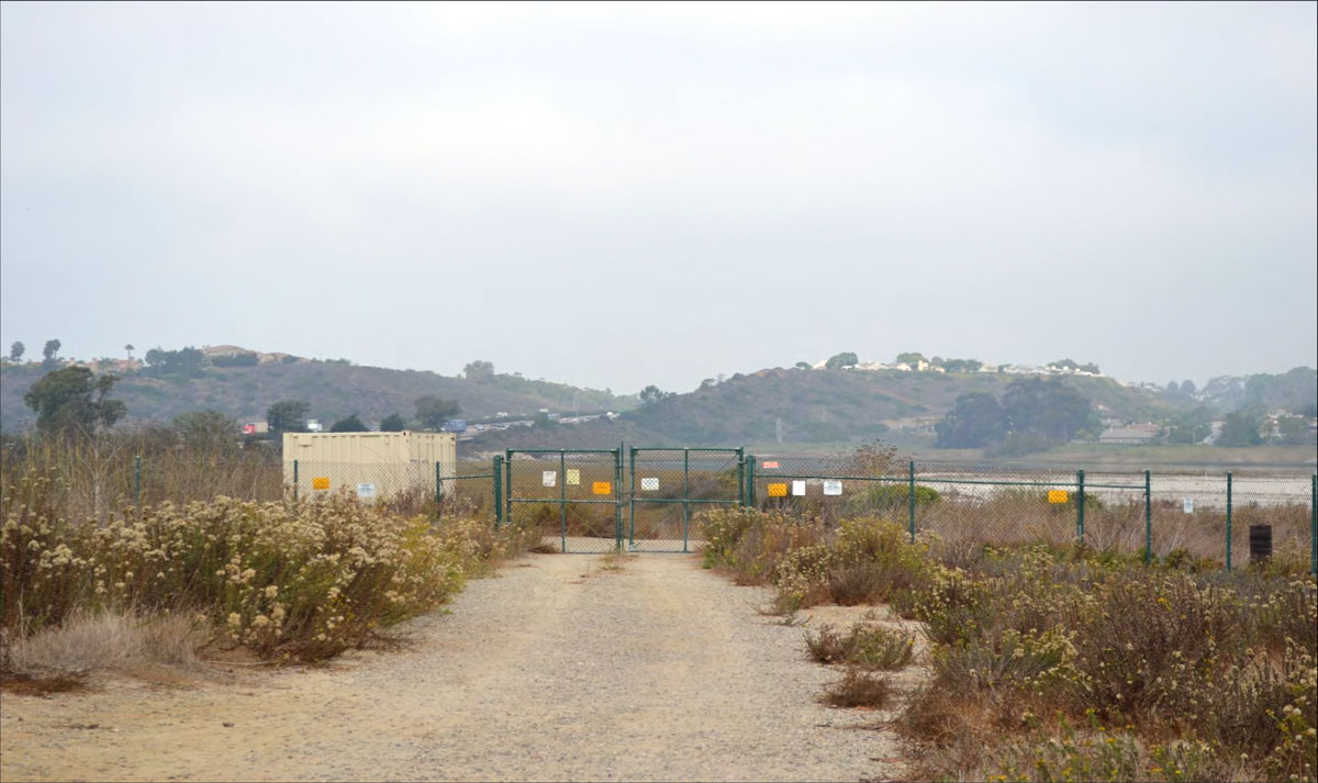
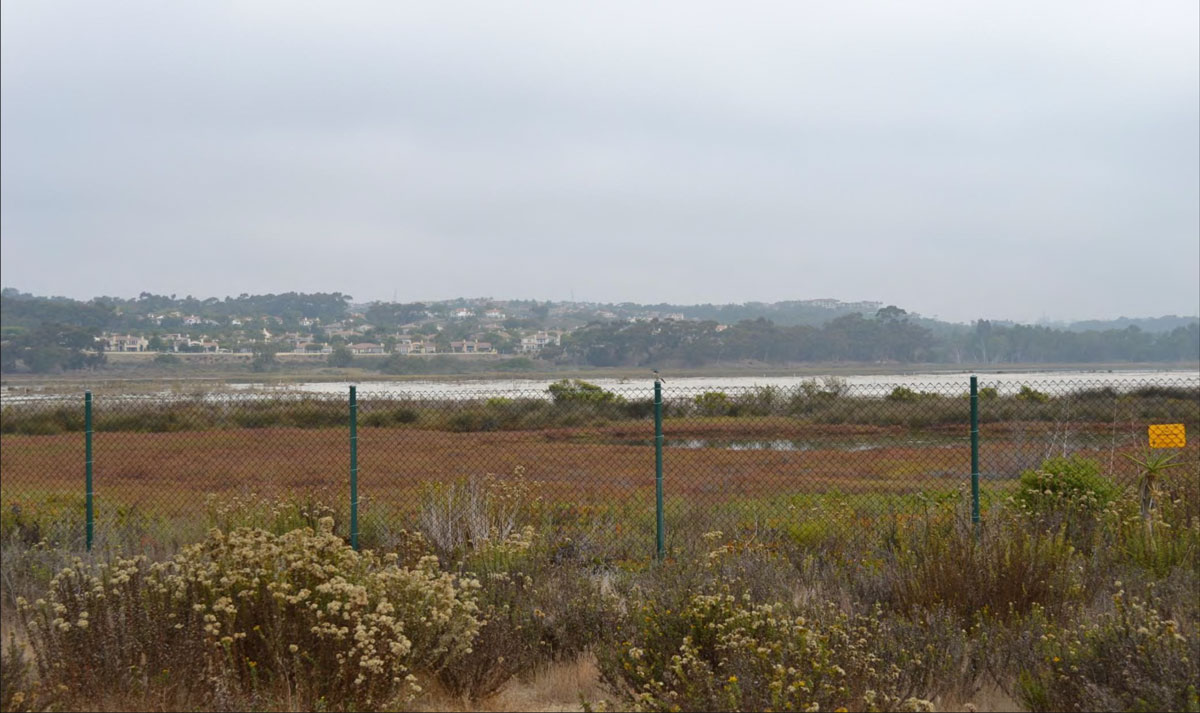
SB-02
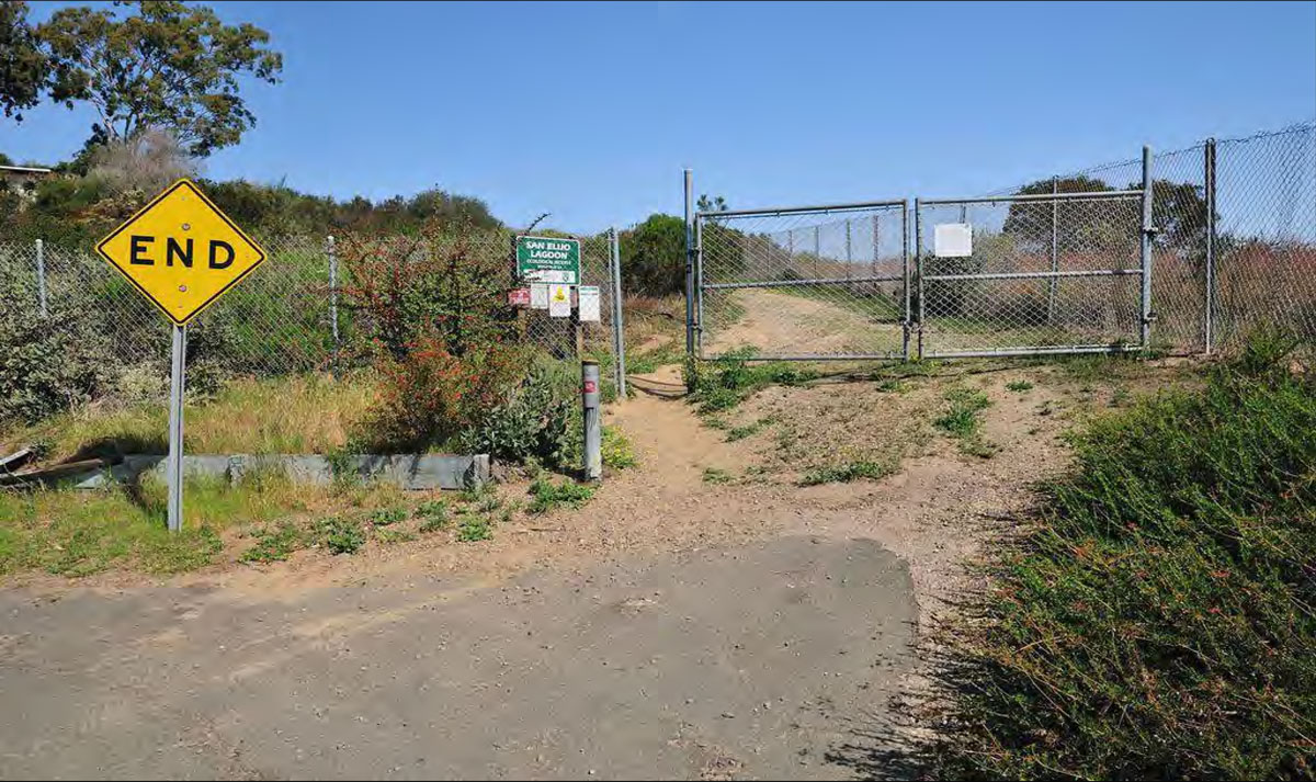
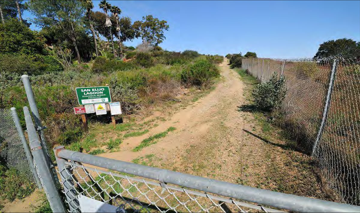
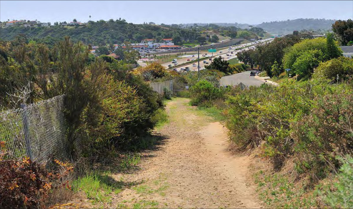
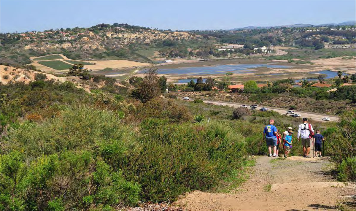
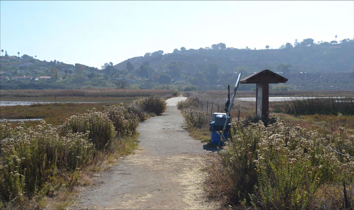
Northern View from Public Trail Toward San Elijo Lagoon from Solana Hills Drive
9
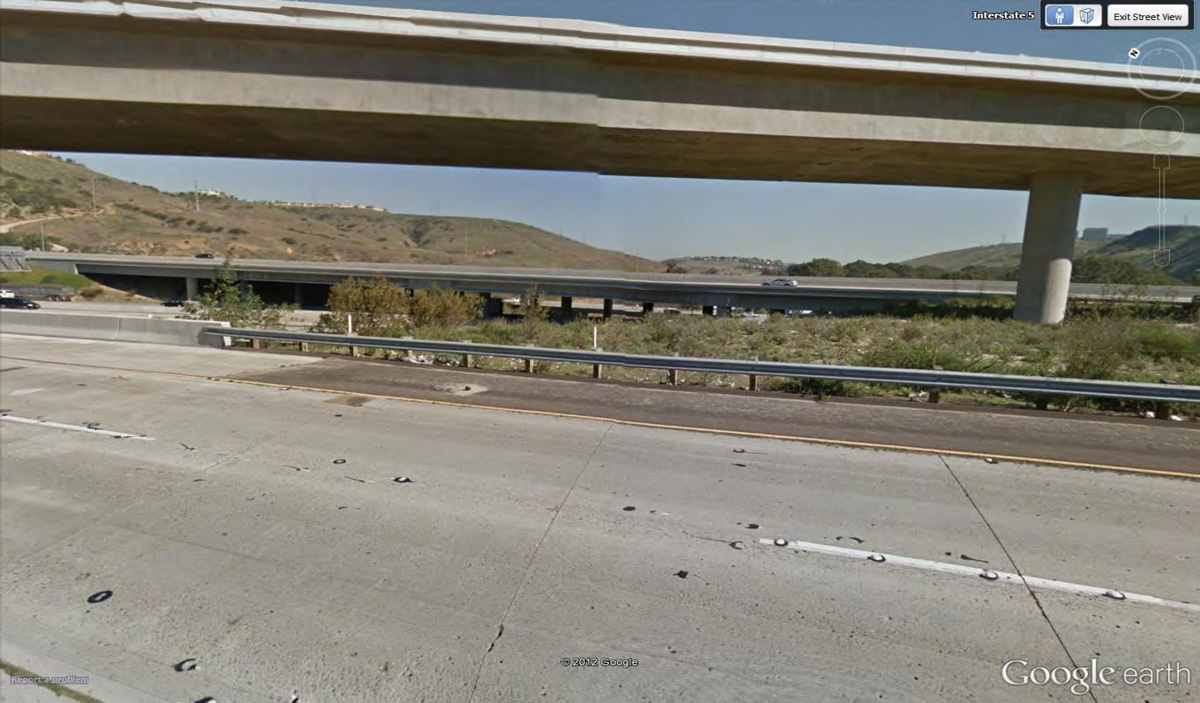
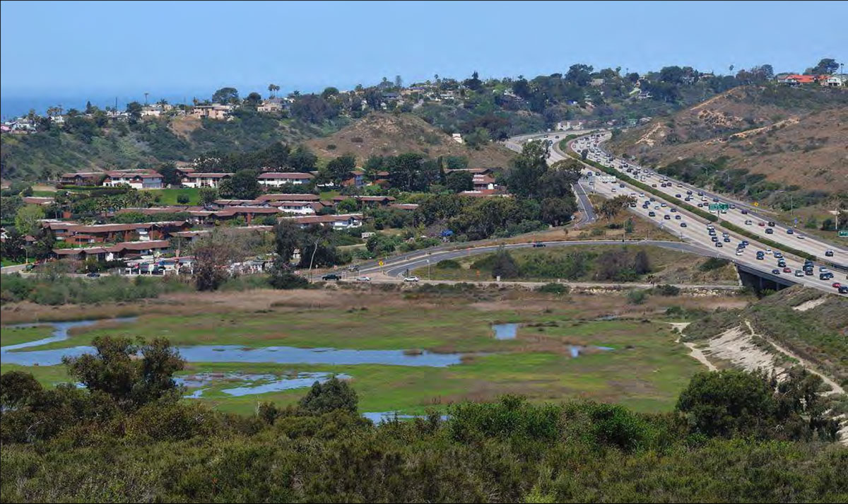
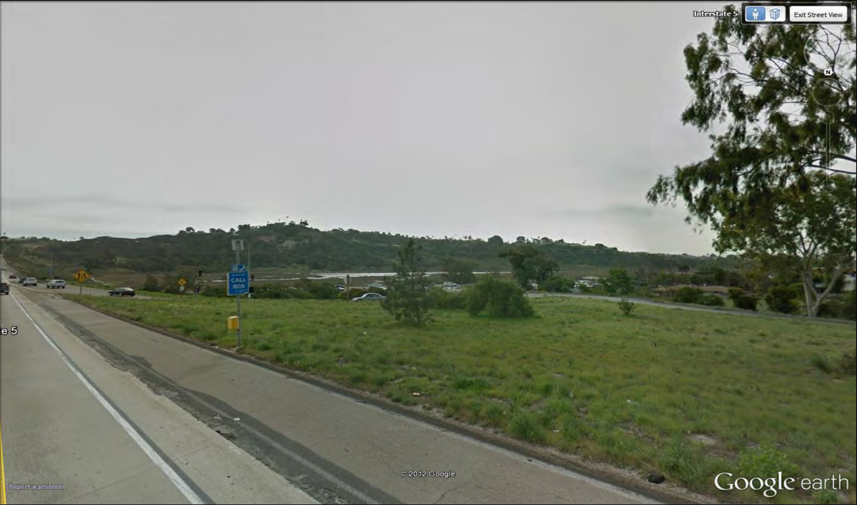
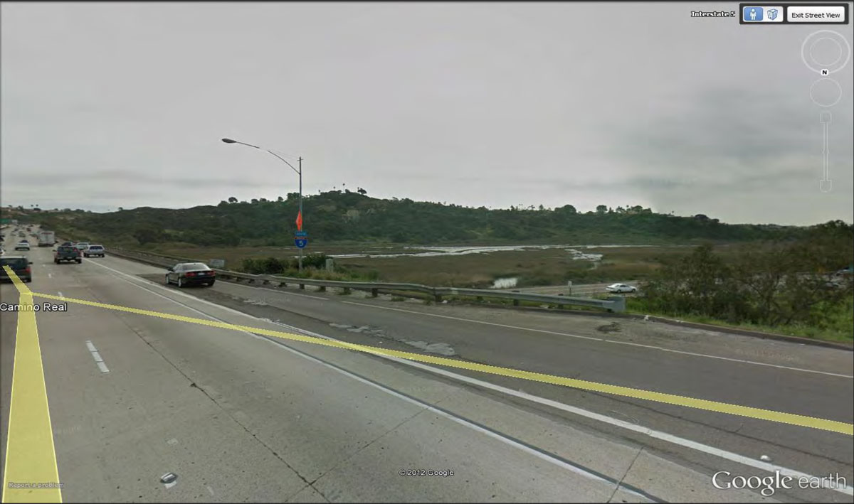
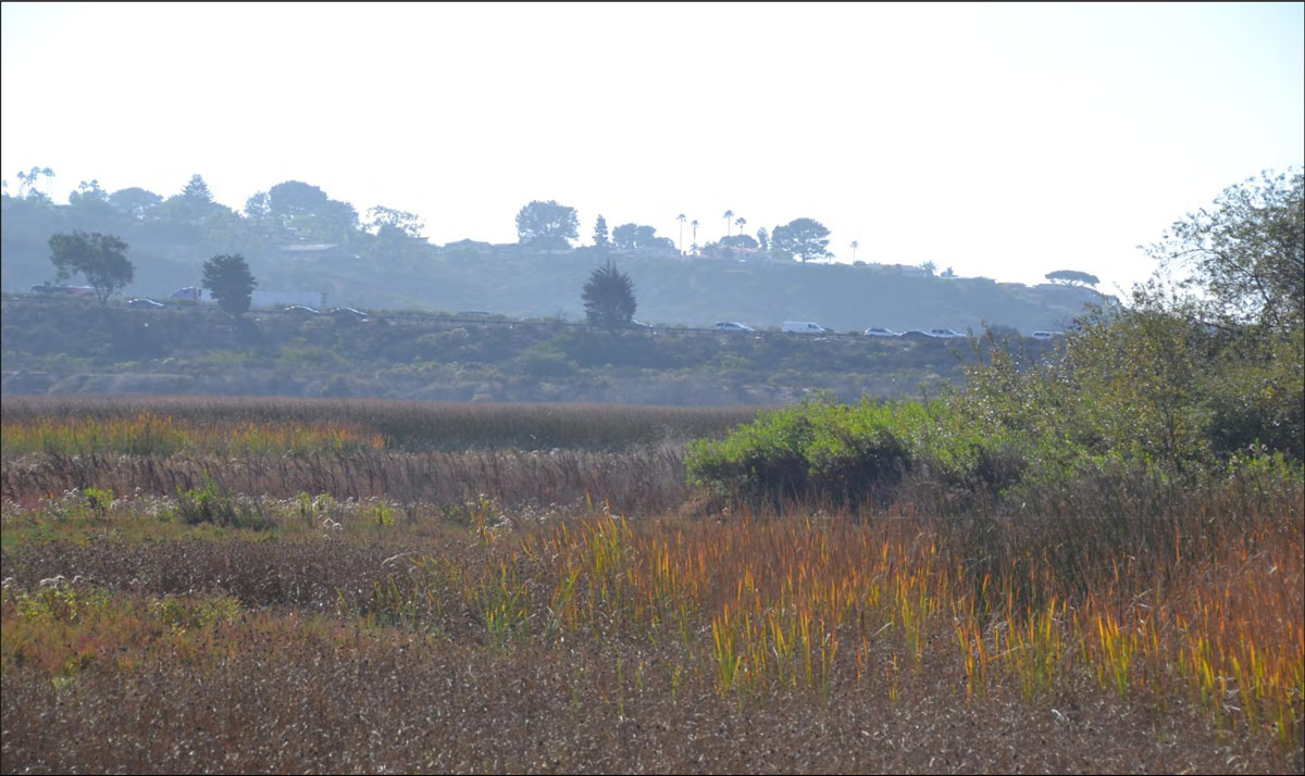
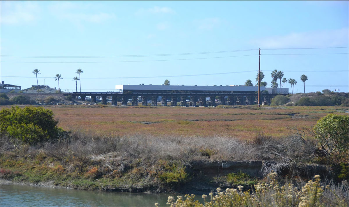
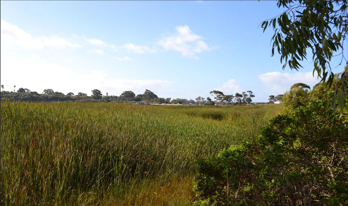
City of Solana Beach: San Elijo Lagoon
SB-03
Western/Eastern views from I-5 Including the Pacific Ocean, San Elijo Lagoon and Coastal and Inland Natural Coastal Landforms
17
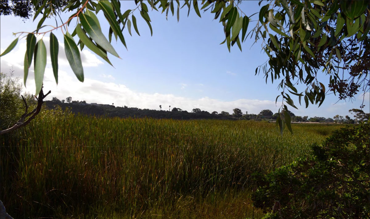
City of Encinitas: San Elijo Lagoon
EC-01
Western/Eastern views from I-5 Including the Pacific Ocean, San Elijo Lagoon and Coastal and Inland Natural Coastal Landforms
* See SB-03
EC-02
Views from Public Trails Located within San Elijo Valley that Include Proposed I-5 Improvements
* See SB-03
EC-03
Western/Eastern Views from Manchester Ave Across Lagoon Toward I-5
10
EC-04
Western/Northern Views from Existing Scenic Overlook on I-5
5
EC-05
Views from Encinitas Community Park
3
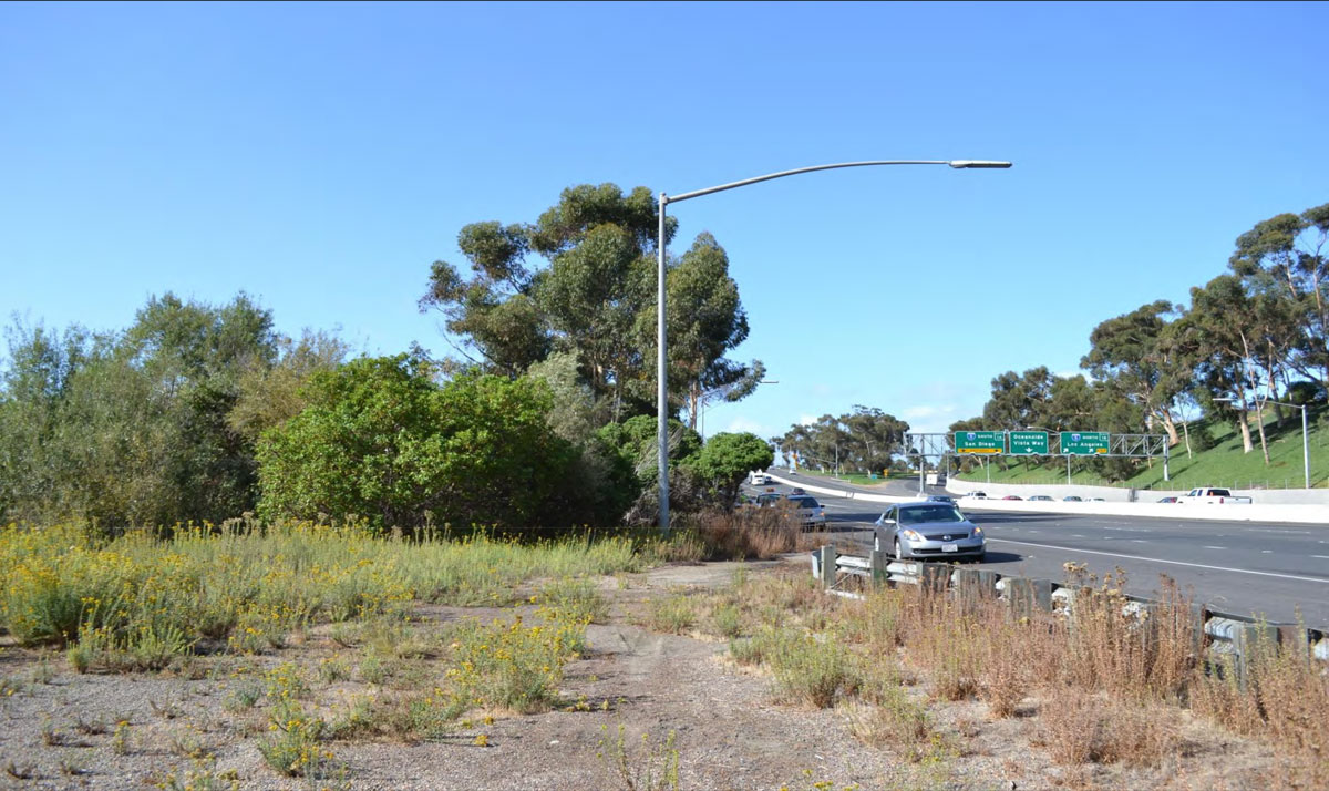
City of Encinitas: Uplands
EC-06
Western Views from I-5 Including the Pacific Ocean (Santa Fe and Encinitas Interchanges)
6
EC-07
Western views of Pacific Ocean from Requeza Public Trail
5
EC-08
Western/Eastern Views from I-5 (Between Manchester/Birmingham and Leucadia/La Costa Exits) of Coastal and Inland Natural Coastal Landforms
13
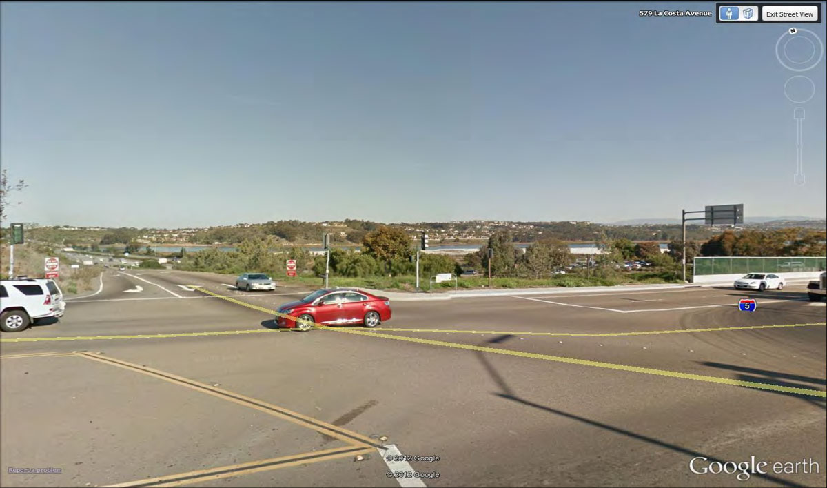
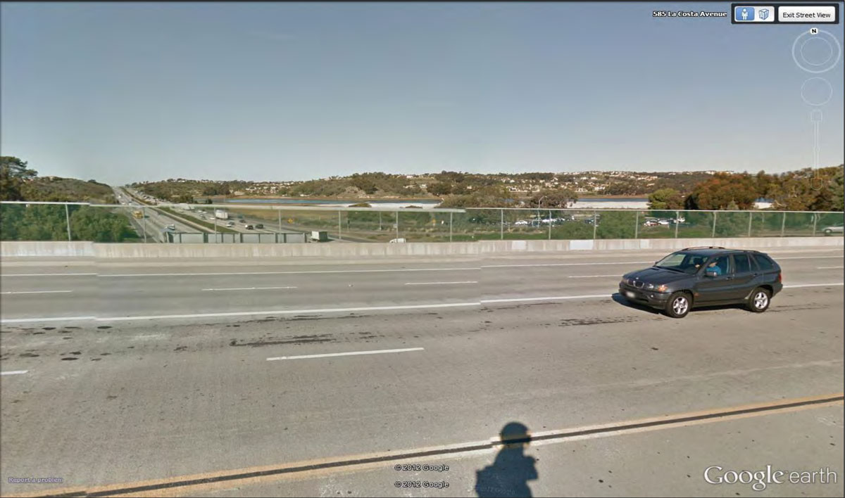
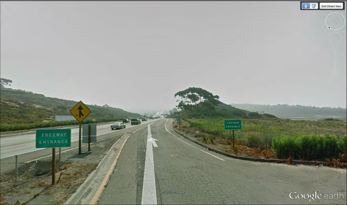
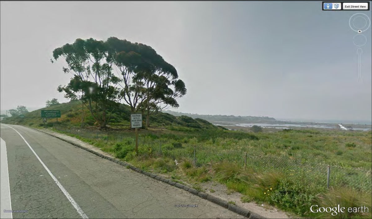
City of Encinitas: Batiquitos Lagoon
EC-09
Western/Eastern Views from I-5 Including the Pacific Ocean, Batiquitos Lagoon and Natural Coastal Landforms
12
EC-10
Northwestern Views from La Costa Avenue Across Lagoon Toward I-5
4
City of Encinitas: Local Coastal Program
EC-11
San Elijo Lagoon (I-5/Manchester Avenue Intersections)
* See EC-03
EC-12
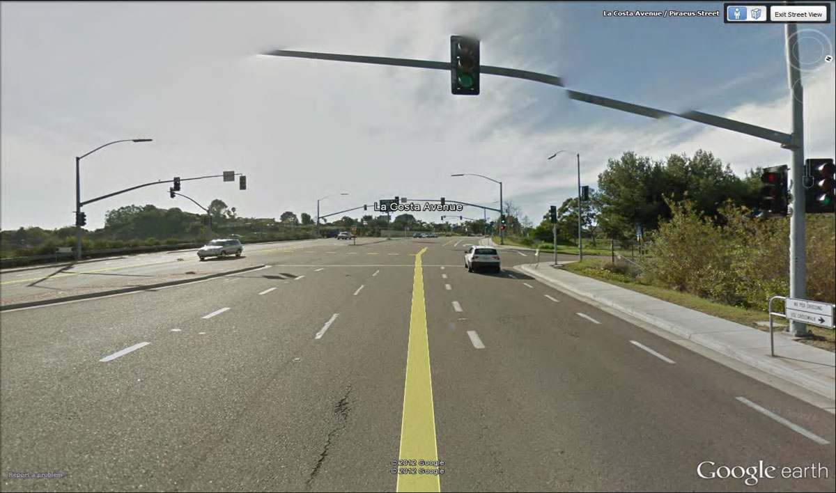
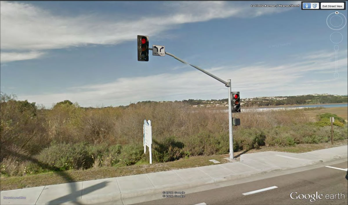
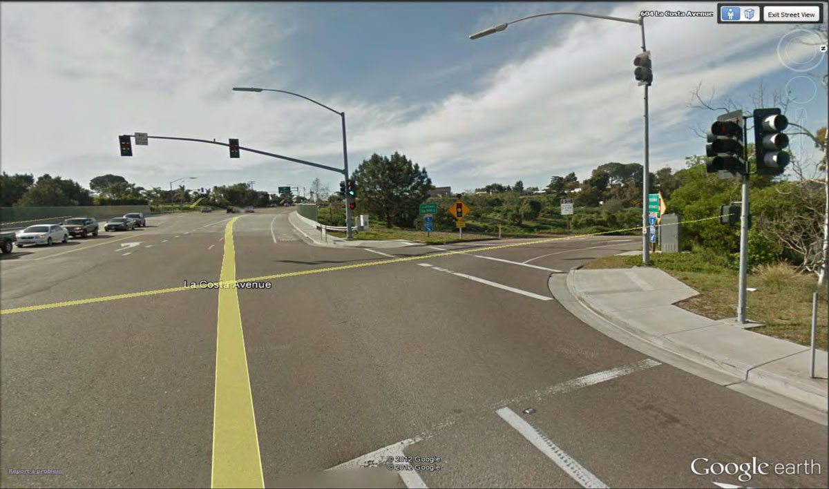
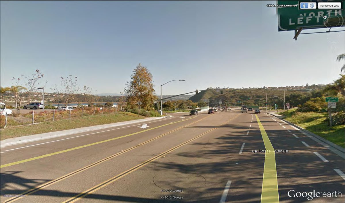
Northeast/Northwest Corner of I-5 and La Costa Avenue
8
EC-14
Existing Vista Point on Southbound I-5 (north of Manchester Avenue)
2
City of Carlsbad: Batiquitos Lagoon
CB-01
Western/Eastern Views from I-5 Including the Pacific Ocean, Batiquitos Lagoon and Coastal and Inland Natural Coastal Landforms
* See EC-09
CB-02
Views from Public Trails Along Northern Lagoon Perimeter Include Proposed I-5 Improvements
11
CB-03
Eastern Views from Public View Point at the End of Navigator Circle Across Lagoon Toward I-5
4
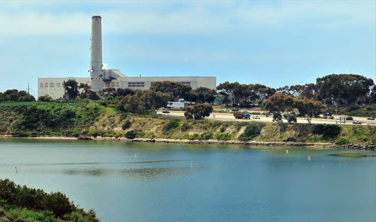
City of Carlsbad: Agua Hedionda Lagoon
CB-04
Western/Eastern Views from I-5 Including Agua Hedionda Lagoon and Coastal and Inland Natural Coastal Landforms
10
CB-05
Views from Public Trails Along Lagoon Perimeter that Include Proposed I-5 Improvements
8
CB-06
Views from Public Recreation Areas (YMCA facilities) in Central/East Basins that Include Proposed I-5 Improvements
* See CB-05
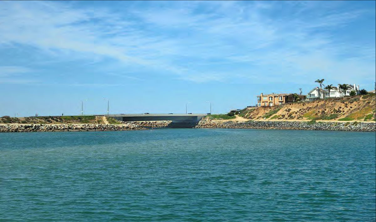
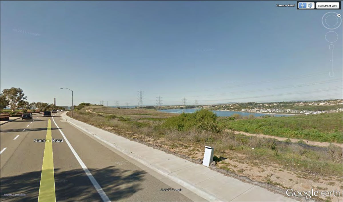
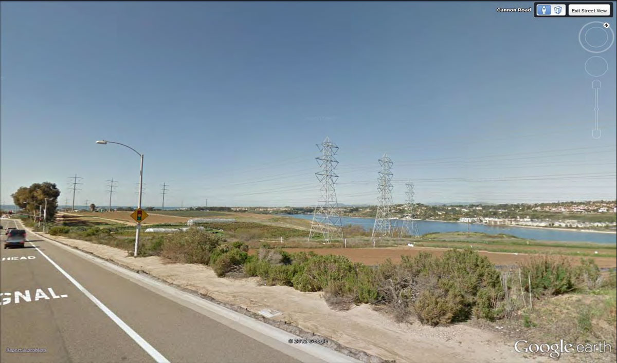
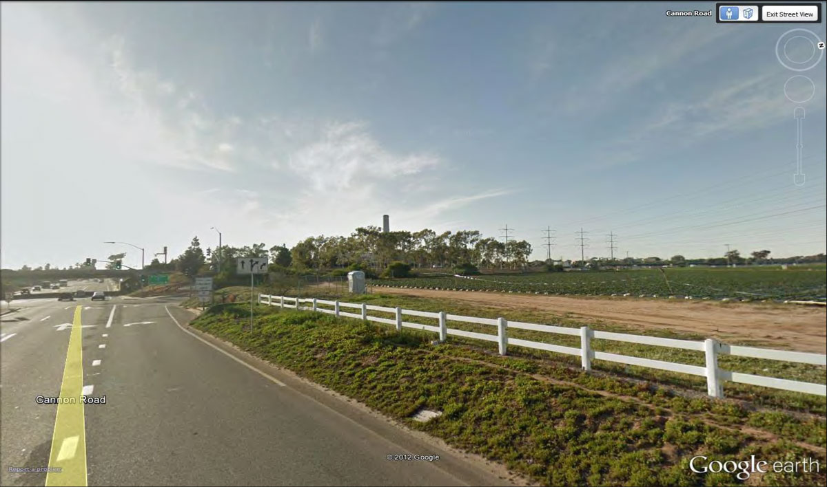
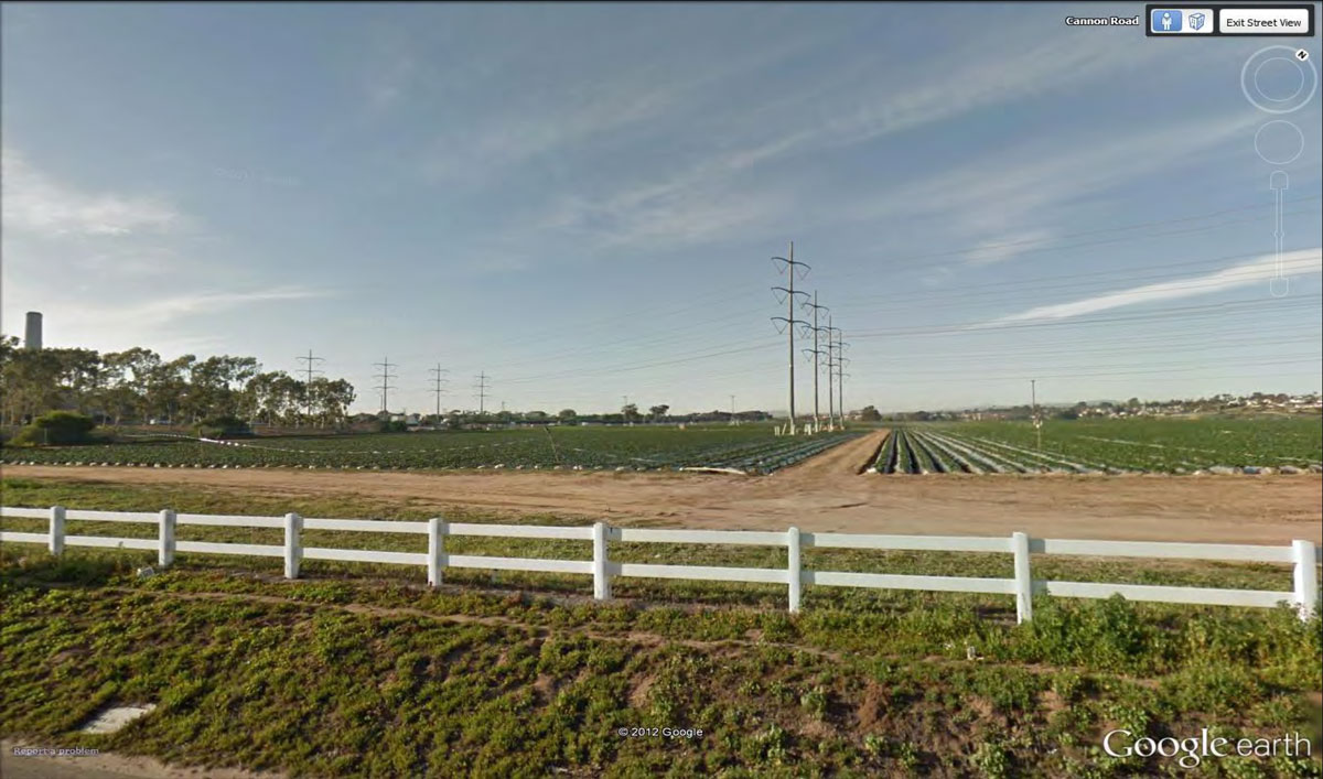
CB-07
Northwestern Views from Cannon Road Across Lagoon/Open Space Toward I-5
5
City of Carlsbad: Buena Vista Lagoon
CB-08
Western/Eastern Views from I-5 Including Buena Vista Lagoon and Coastal and Inland Natural Coastal Landforms
* See OC-01
CB-09
Northern/Western/Eastern Views from Jefferson Street Across Lagoon Toward I-5
7
CB-10
Eastern Views from State Street/Carlsbad Boulevard Across Lagoon Toward I-5
3
OC-04
Eastern Views from Public Trail System Extending Along Lagoon Perimeter East of Audubon Center Toward I-5
5
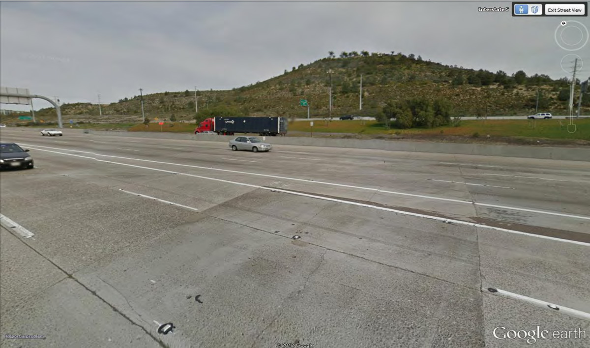
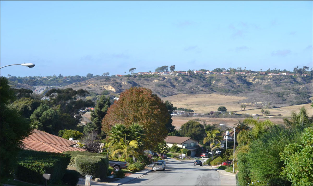
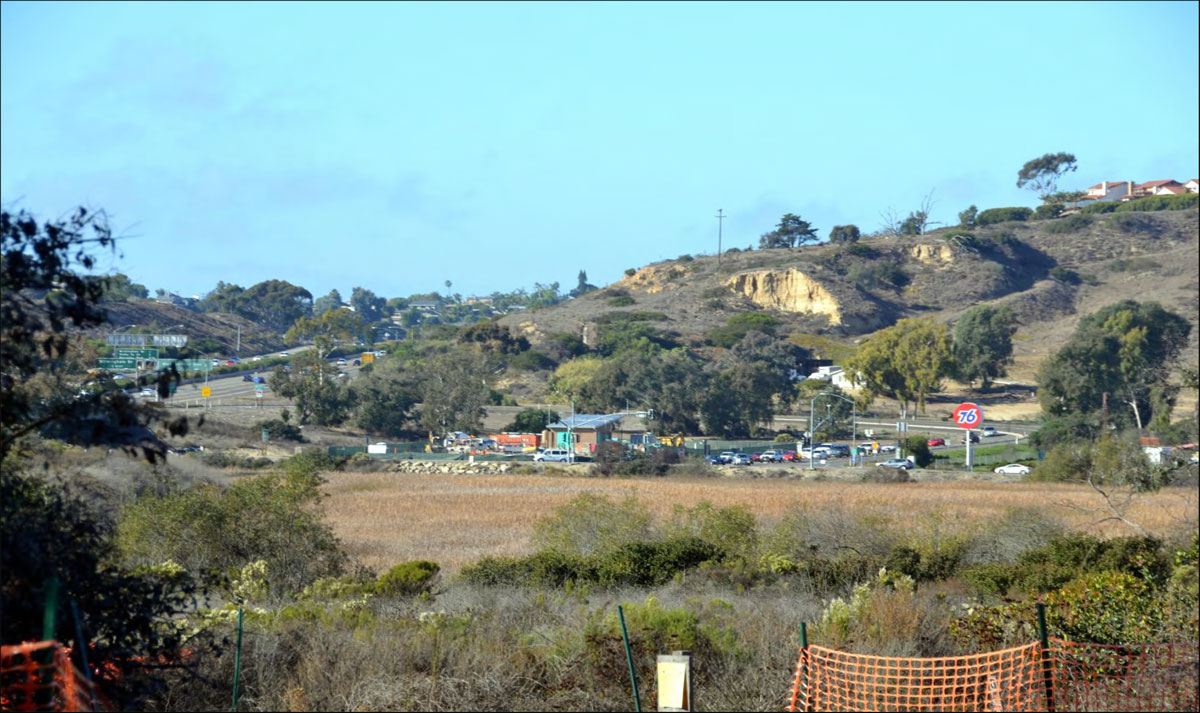
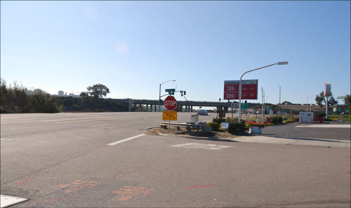
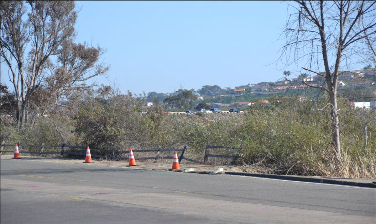
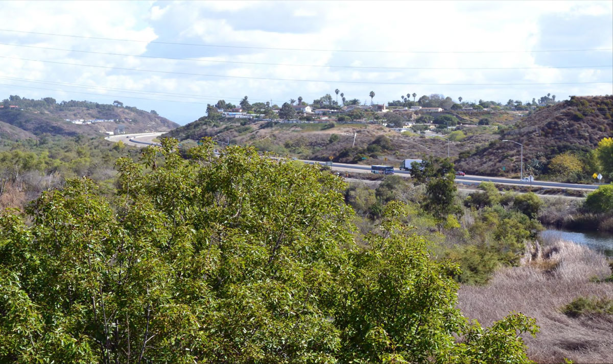
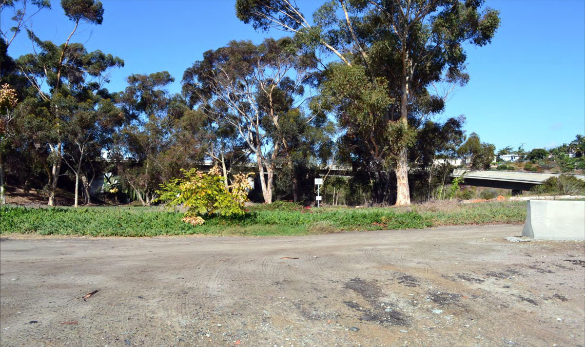
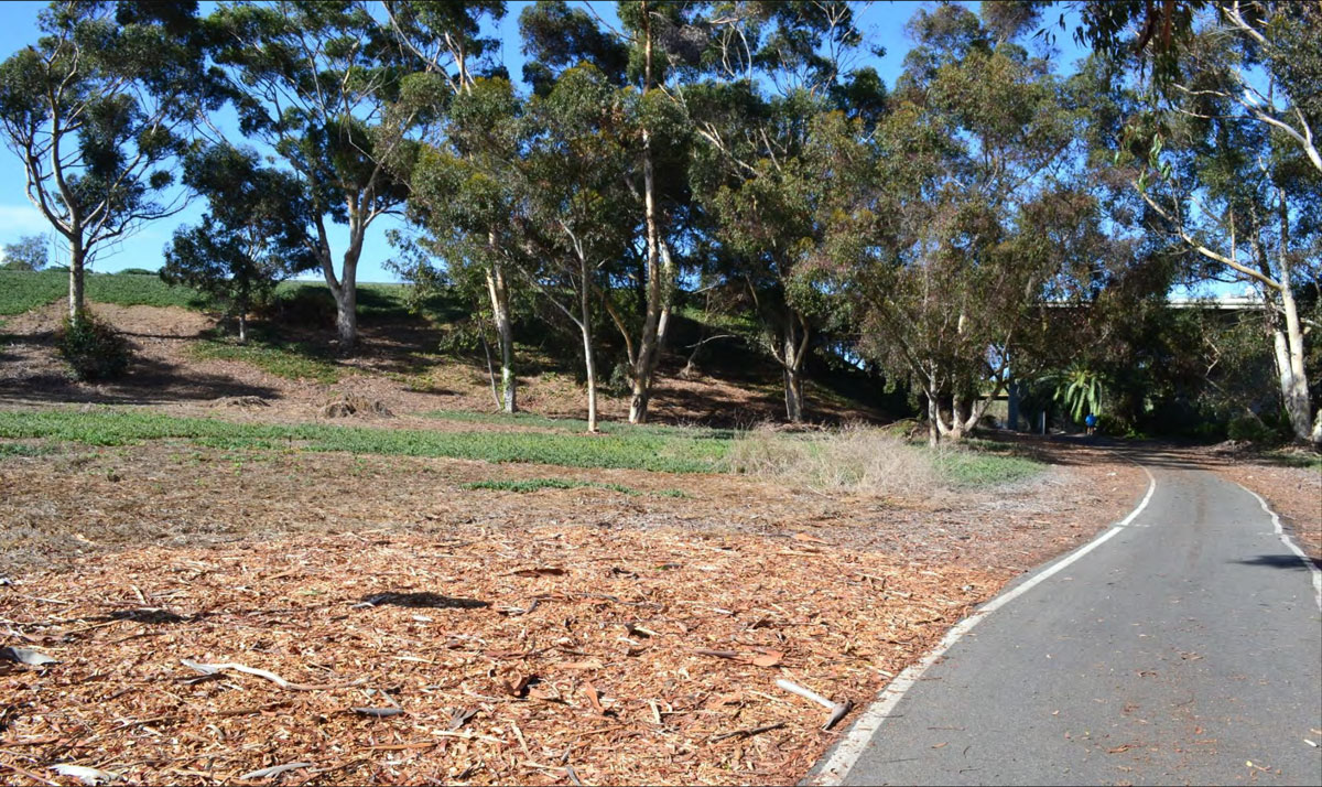
City of Oceanside: San Luis Rey River Valley
OC-05
Western/Eastern Views from I-5 Including the Pacific Ocean, San Luis Rey River Valley, and Coastal and Inland Natural Coastal Landforms
7
OC-06
Northern/Western Views from SR 76 Across San Luis Rey River Valley Toward I-5
1
OC-07
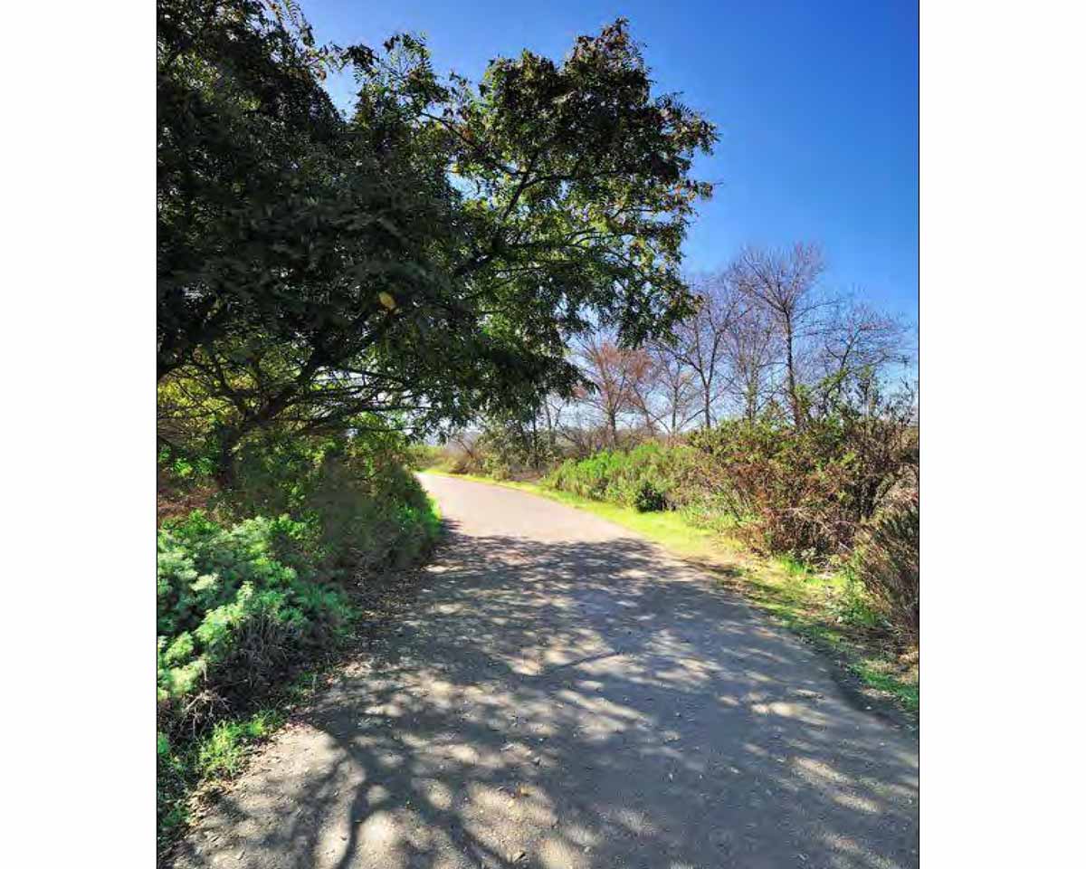
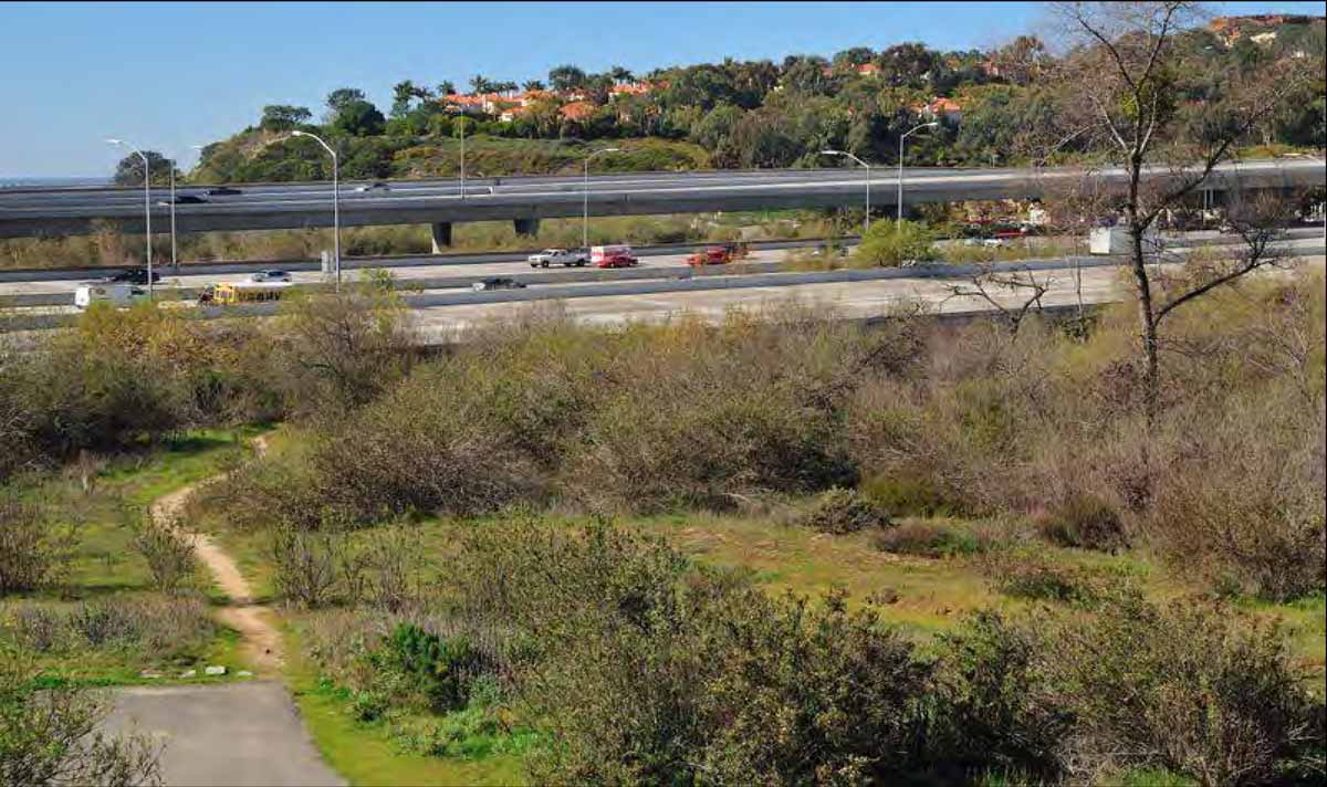
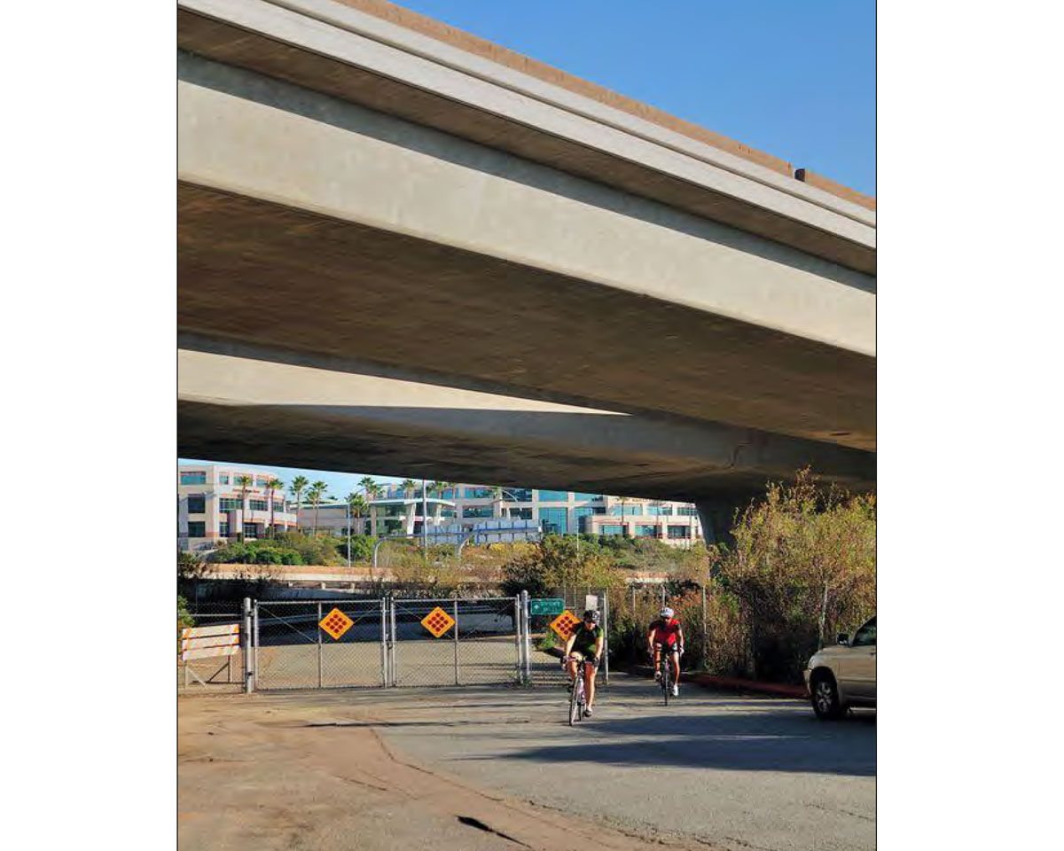
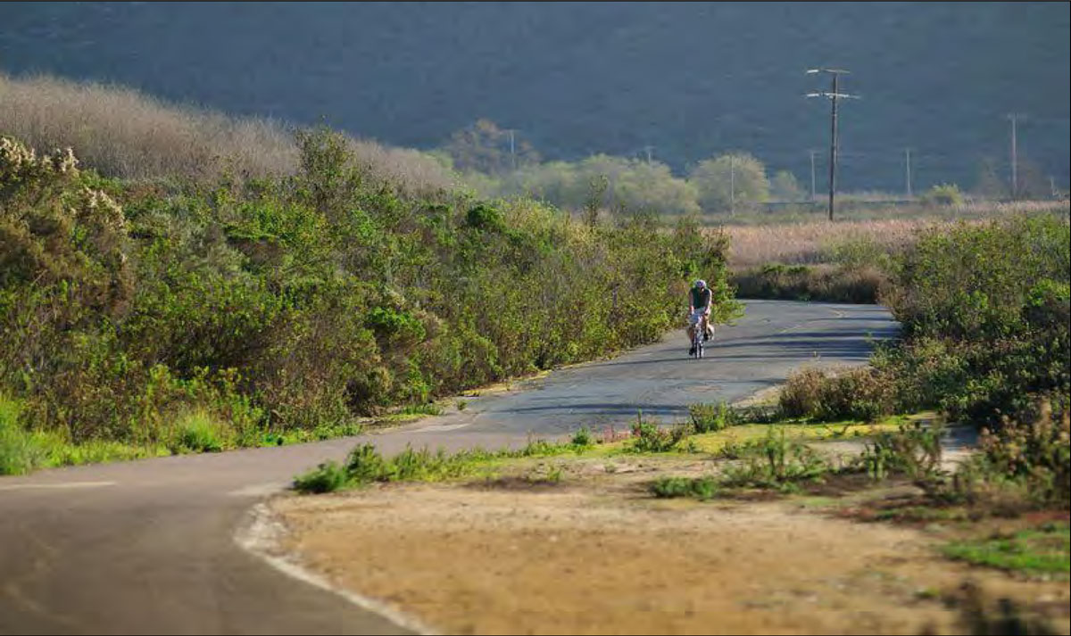
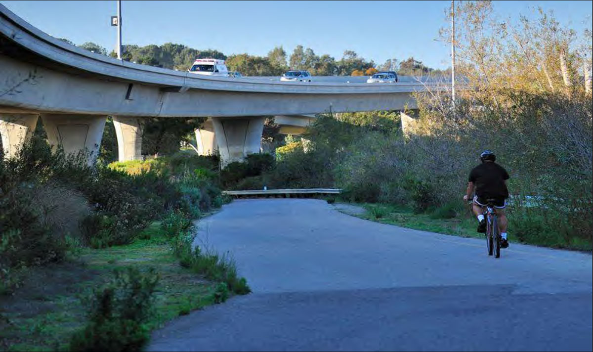
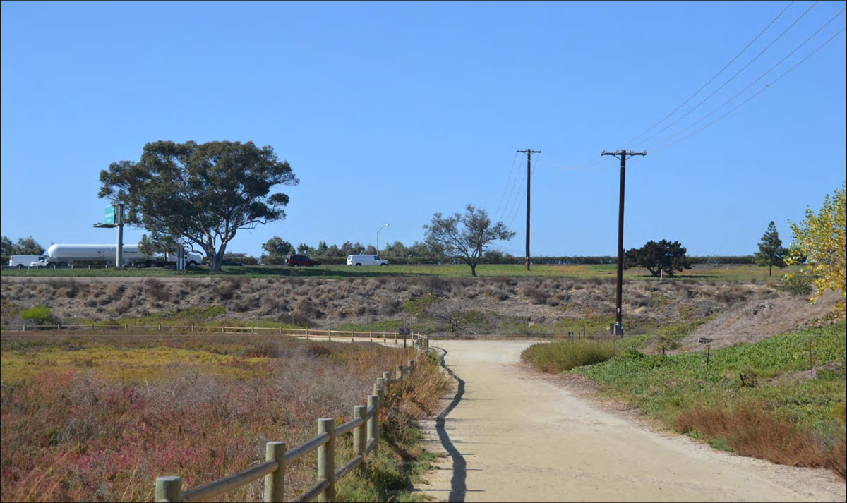
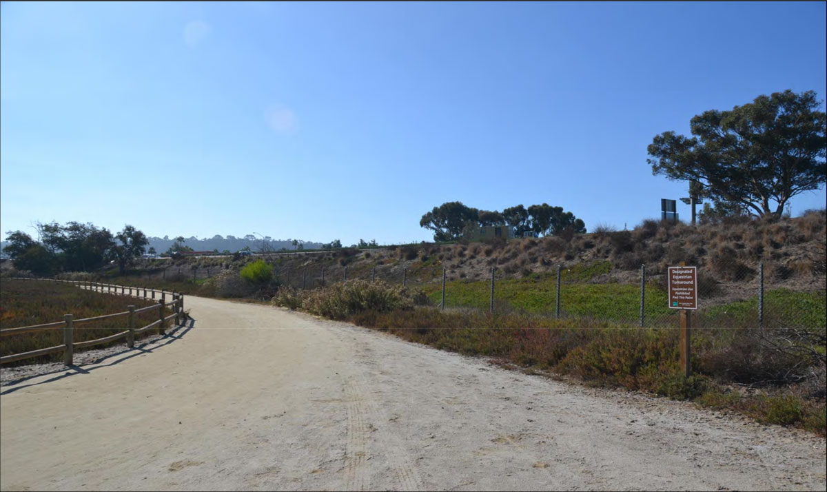
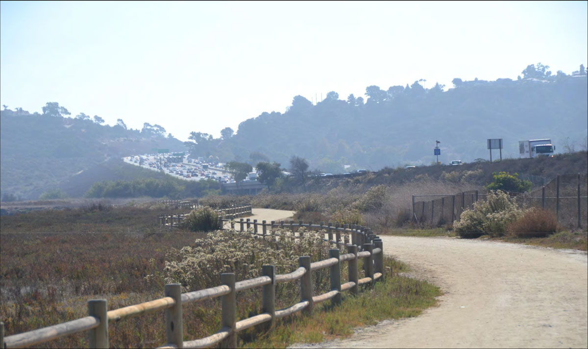
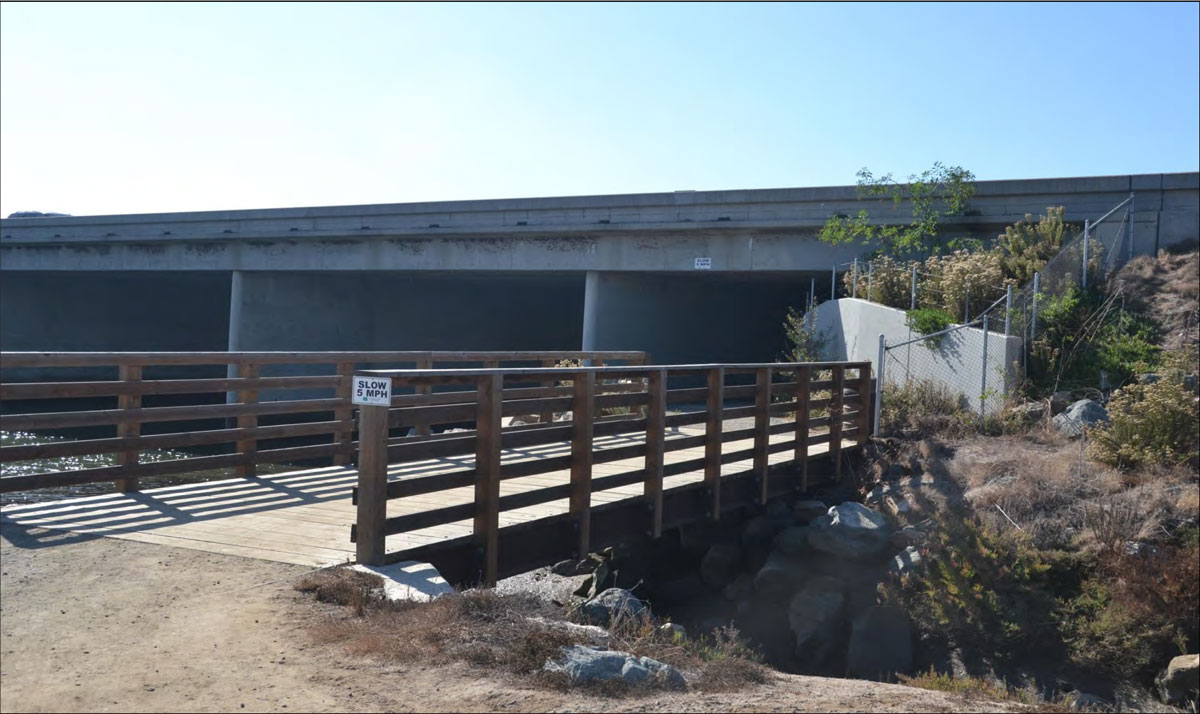
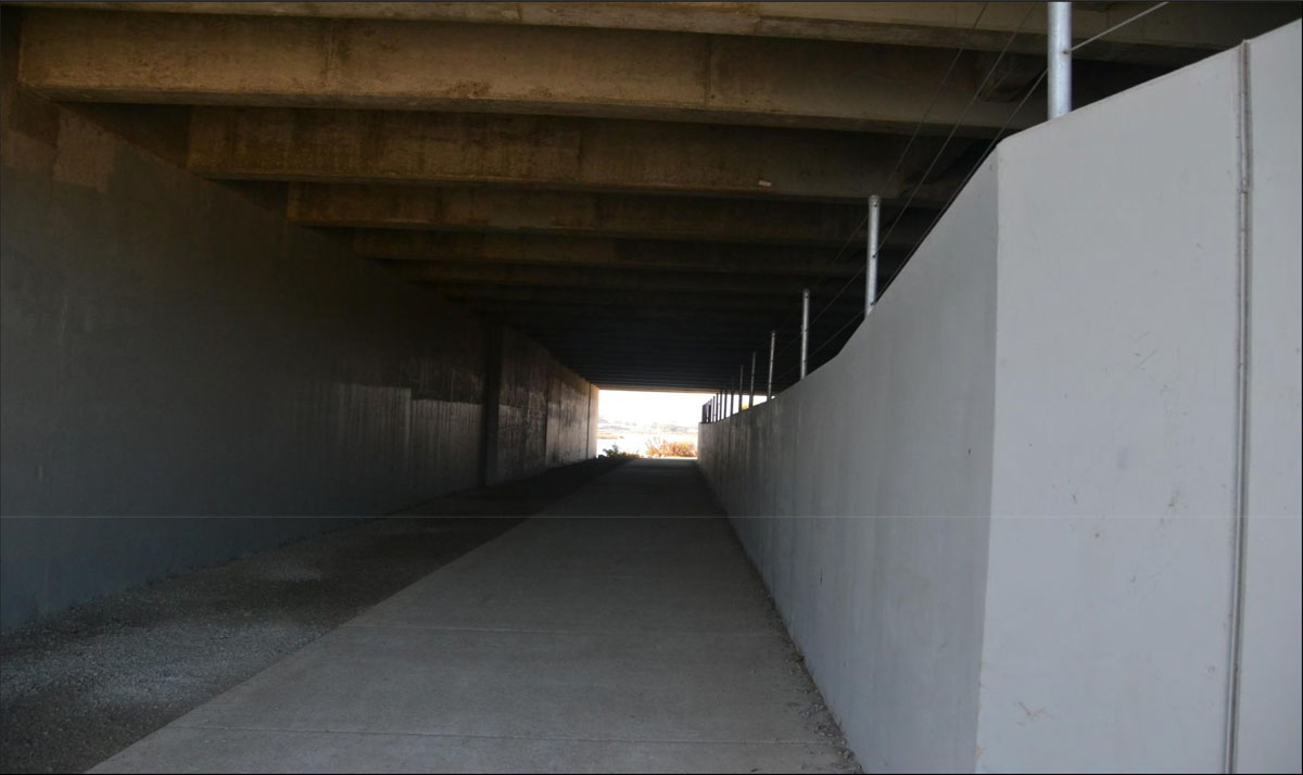
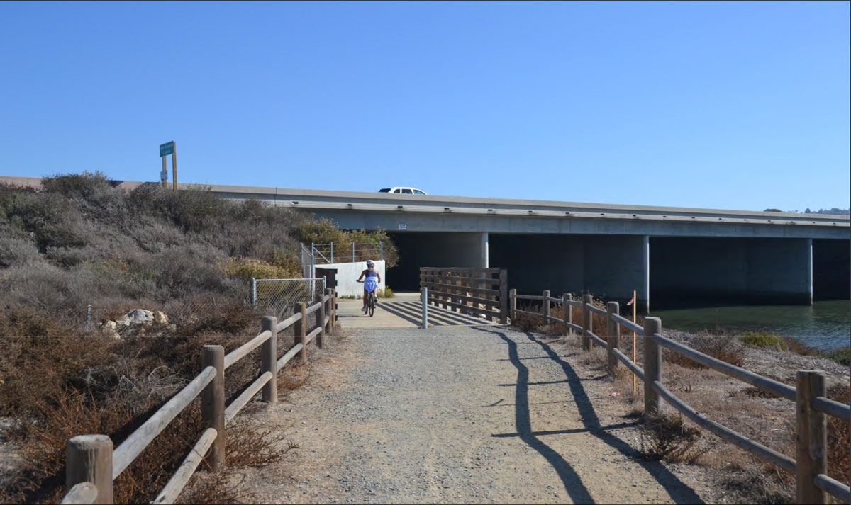
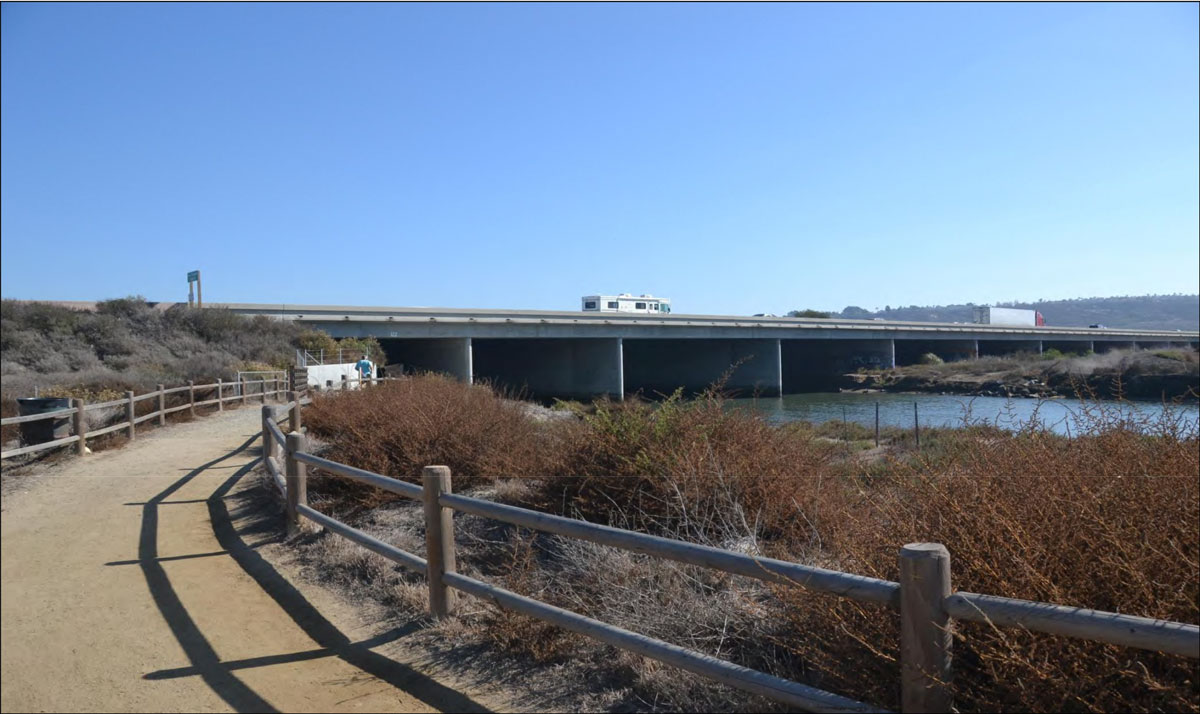
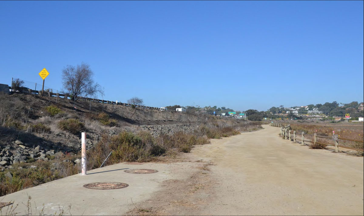
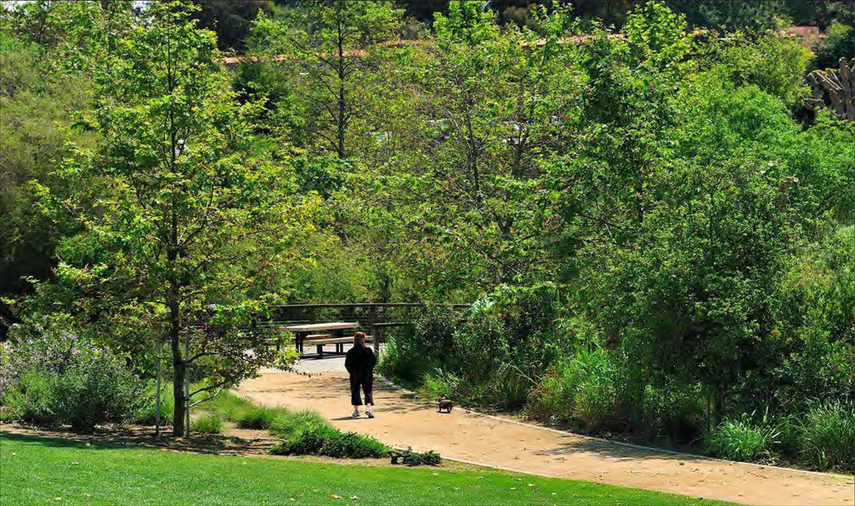
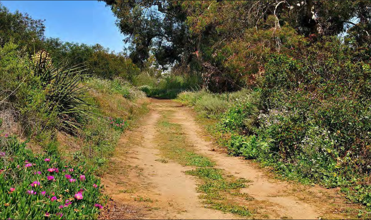
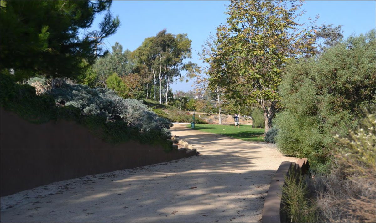
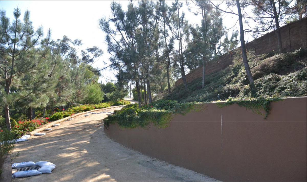
Views from Public Trails (San Luis Rey River Trail) within San Luis Rey River Valley that Include Proposed I-5 Improvements
8
OC-08
Eastern Views from Pacific Street Across River Valley Toward I-5
2
City of Oceanside: Local Coastal Program
OC-09
San Luis Rey River (Park & Ride or at Hiking/Biking Trail)
1. Placement of HOV/Managed Lanes advance warning signs as outlined Chapter 2G of the 2012
California Manual on Uniform Traffic Control Devices (CA MUTCD).
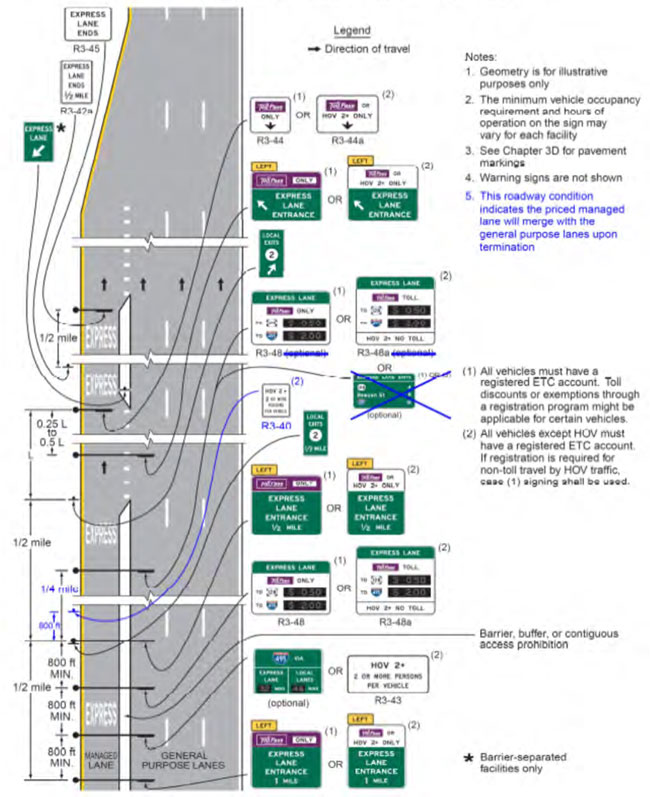
Minimum advance sign placement is about 1 mile from entry point of the Intermediate Access Points (IAPs) with advance signs to IAP entrance placed in 0.5 mile increments. Tolling signs are placed (at minimum) about 0.25 mile and 0.65 mile from the IAP entrance, respectively. Sign dimensions are summarized in Table 2G-1. Note that the figure below show only regulatory (guide) signs as they apply to IAPs.
Figure 2G-24
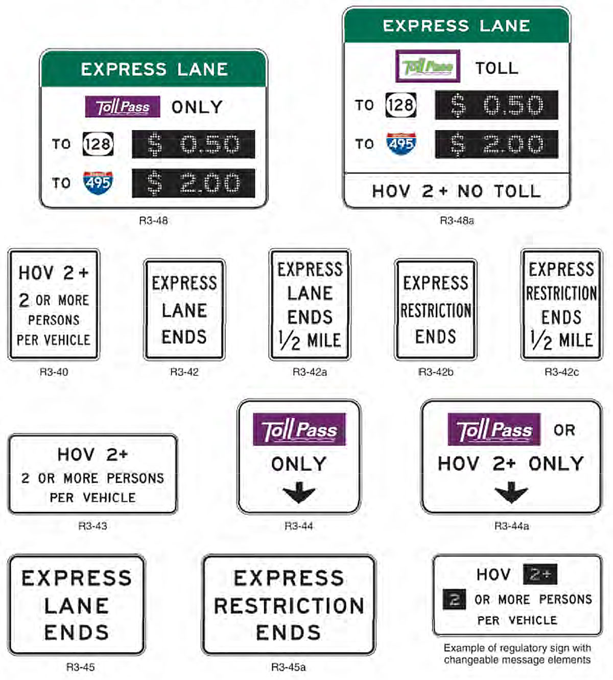
- Example of Signing for the Intermediate Entry to, Egress from, and End of Access-Restricted Priced Managed Lanes. Figure 2G-17 – Regulatory Signs for Managed Lanes
- Notes:
The ETC pictograph shown is an example only. The pictograph for the toll facility's adopted ETC system shall be used.
Changeable message sign elements shall be used for the numerals displayed for the variable tolls.
Figure 2G-18 – Examples of Guide Signs for Entrances to Priced Managed Lanes
- Notes:
The ETC pictographs shown are examples only. The pictograph for the toll facility's adopted ETC system shall be used.
The examples shown are for facilities on which registration in a toll account program is required for toll payments.
2. Minimum Sign and Plaque sizes.
Dimensions of signing outlined on Figure 2G-17 and Figure 2G-24 above are shown on Table 2G-1 with the appropriate signs and highway facility type marked *. See
Figure 2G-24 for sign designations. Dimensions are in inches.
Table 2G-1 – Managed and Preferential Lanes Sign and Plaque Minimum Sizes
Notes:
1. Larger signs may be used when appropriate.
2.
Dimensions in inches are shown as width x height.
Sign or Plaque
Sign Designation
Section
Conventional Road Single Lane
Conventional Road Multi-Lane
Expressway
Freeway
Oversized
Preferential Lane Periods of Operation (post-mounted)
R3-11 series
2G.05
30 x 42
30 x 42
36 x 60
36 x 60
78 x 96
Preferential Lane Ahead of End (post-mounted)
R3-12 series
2G.06
30 x 42
30 x 42
36 x 60
36 x 60
78 x 96
Preferential Lane Vehicle Occupancy Definition (overhead)
R3-13,13a
2G.04
66 x 36
66 x 36
84 x 48
144 x 78
144 x 78
HOV Lane Periods of Operation (overhead)
R3-14,14a,14b
2G.05
72 x 60
72 x 60
96 x 72
144 x 108
144 x 108
Preferential Lane Periods of Operation (overhead)
R3-14c
2G.05
90 x 60
90 x 60
108 x 72
156 x 102
168 x 102
HOV Lane Ahead (overhead)
R3-15
2G.06
66 x 36
66 x 36
84 x 48
102 x 60
102 x 60
HOV Lane Begins XX Miles (overhead)
R3-15a
2G.06
78 x 42
78 x 42
102 x 54
132 x 72
132 x 72
HOV Lane Ends (overhead)
R3-15b,15c
2G.07
66 x 36
66 x 36
84 x 48
102 x 60
102 x 60
Preferential Lane Ahead or Ends (overhead)
R3-15d,15e
2G.07
42 x 36
42 x 36
54 x 48
72 x 60
72 x 60
Priced Managed Lane Vehicle Occupancy Definition (post-mounted)
R3-40
2G.17
–
–
54 x 66
54 x 66
66 x 78
Priced Managed Lane Ends (post-mounted)
R3-42,42b
2G.17
–
–
48 x 60
48 x 60
60 x 78
Priced Managed Lane Ends Advance (post-mounted)
R3-42a,42c
2G.17
–
–
48 x 66
48 x 66
60 x 84
Priced Managed Lane Vehicle Occupancy Definition
R3-43
2G.17
–
–
138 x 66
138 x 66
–
Priced Managed Lane Periods of Operation (overhead)
R3-44
2G.17
–
–
90 x 84
90 x 84
–
Priced Managed Lane Periods of Operation (overhead)
R3-44a
2G.17
–
–
132 x 84
132 x 84
–
Priced Managed Lane Ends (overhead)
R3-45
2G.17
–
–
90 x 66
90 x 66
–
Priced Managed Lane Ends (overhead)
R3-45a
2G.17
–
–
114 x 66
114 x 66
–
Priced Managed Lane Toll Rate
R3-48
2G.17
–
–
Varies
Varies
–
Priced Managed Lane Toll Rate
R3-48a
2G.17
–
–
Varies
Varies
–
HOV (plaque)
W16-11P
2G.09
24 x 12
24 x 12
30 x 18
30 x 18
30 x 18
Preferential Lane Entrance Gore
E8-1
2G.10
–
–
48 x 96
48 x 96
–
Preferential Lane Intermediate Entrance Gore
E8-1a
2G.10
–
–
48 x 84
48 x 84
–
Preferential Lane Entrance Direction (overhead)
E8-2
2G.11
–
–
222 x 72
222 x 72
–
Preferential Lane Entrance Direction (post-mounted)
E8-2a
2G.11
–
–
186 x 108
186 x 108
–
Preferential Lane Entrance Advance
E8-3
2G.11
–
–
186 x 96
186 x 96
–
Preferential Lane Direct Exit Gore
E8-4
2G.15
–
–
60 x 78
60 x 78
–
Preferential Lane Intermediate Egress Direction
E8-5
2G.13
–
–
Varies x 90
Varies x 90
–
Preferential Lane Intermediate Egress Advance
E8-6
2G.13
–
–
Varies x 84
Varies x 84
–
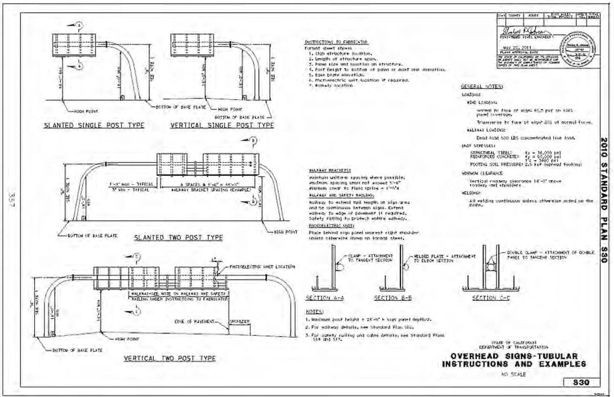
3. Overhead signs.
Caltrans Standard Plans S30 show typical placement and minimum clearance from freeway pavement. Signs and sign structures require a minimum vertical clearance of 18 feet from freeway high point and edge of shoulder, respectively. Tubular overhead signs can be specified as slanted or vertical post.
2010 Standard Plan S30
- Overhead Signs-Tubular Instructions and Examples.
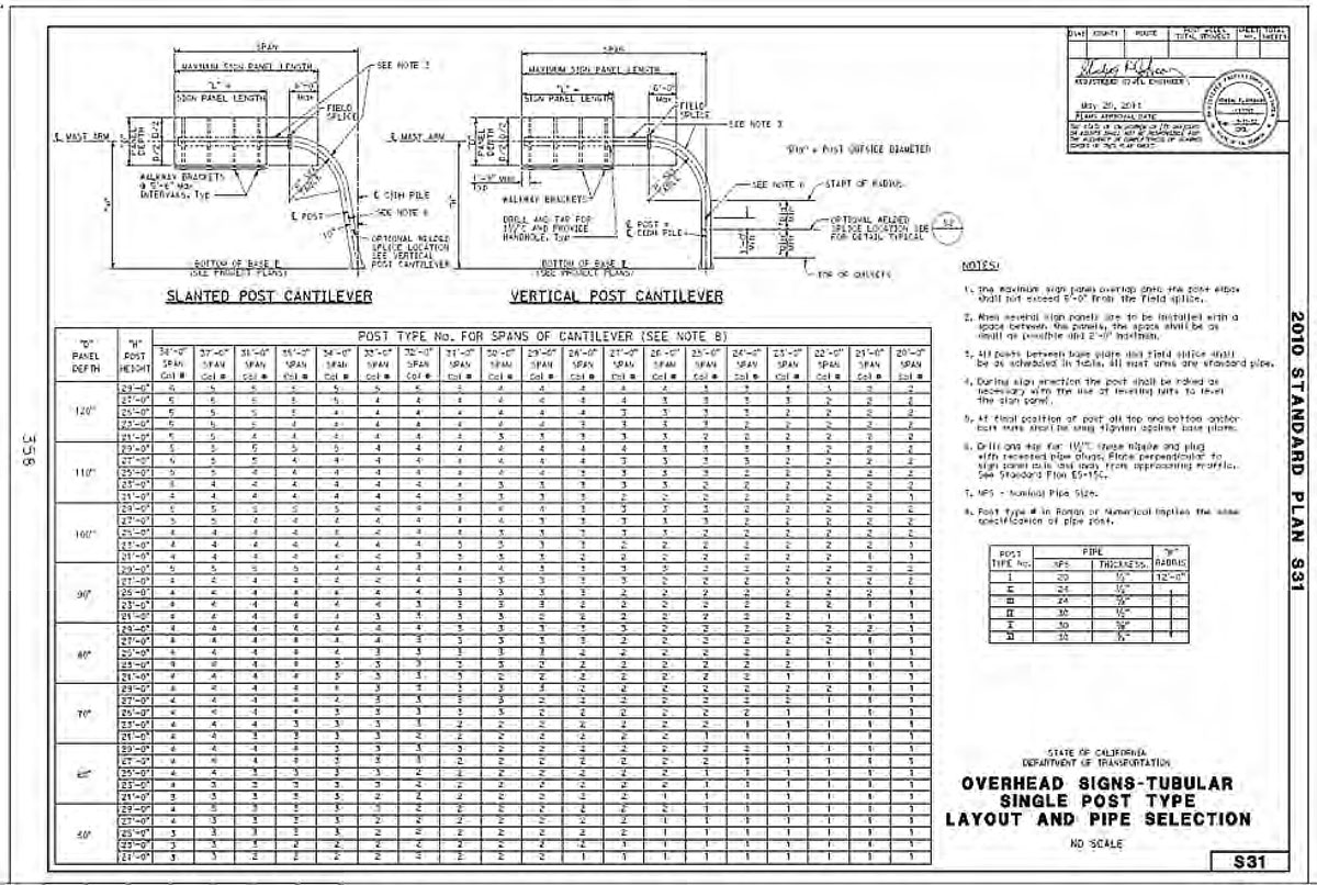
4. Overhead Sign- Single Post Type.
Span (cantilever) range from 20 feet to 38 feet. Height to centerline of mast arm(H) ranges from 21 feet to 29 feet relative to the bottom of base plate and is a function of the sign panel depth(D). Sign panel depth range from 50 inches to 120 inches. H and D in turn would be used to determine the post type and thickness. Please see Standard Plan S31 below for additional details.
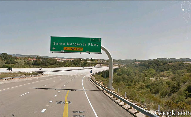
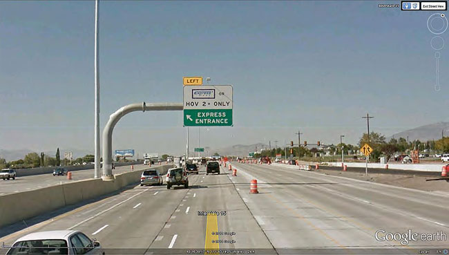
2010 Standard Plan S31 - Overhead Signs-Tubular Single Post Type Layout and Pipe Selection. 5A Photo
- Single post type tubular overhead sign along CA 241. 5B Photo - Single post type tubular overhead sign along I-15 in Utah.
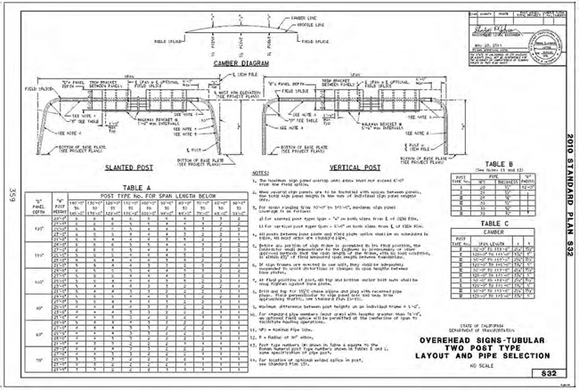
6. Overhead Sign- Two Post Type.
Spans range from 50 feet to 145 feet. Height to centerline of
mast arm(H) ranges from 21 feet to 29 feet relative to the bottom of base plate and is a function of
the sign panel depth(D). Sign panel depth range from 50 inches to 120 inches. H and D in turn
would be used to determine the post type and thickness. Please see Standard Plan S32 below for
additional details.
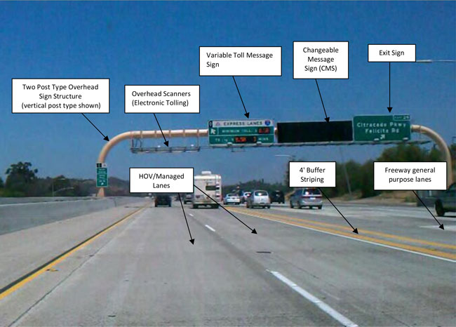
2010 Standard Plan S32 - Overhead Signs-Tubular Two Post Type Layout and Pipe Selection. 7. Photo – Two post type tubular overhead sign along I-15 freeway
- This sign structure includes overhead
scanners, tolling sign, CMS along with the corresponding exit sign. The lane configuration shown in this
photo is similar to the proposed lane configuration for the I-5 North Coast Corridor Project.
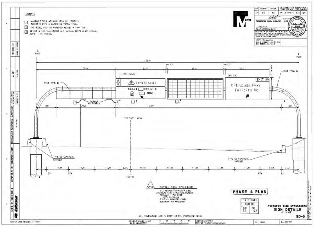
8. Plan showing details and dimensions for the same sign structure shown on the photo above.
Phase 4 Plan - Overhead Sign Structures Sign Details.
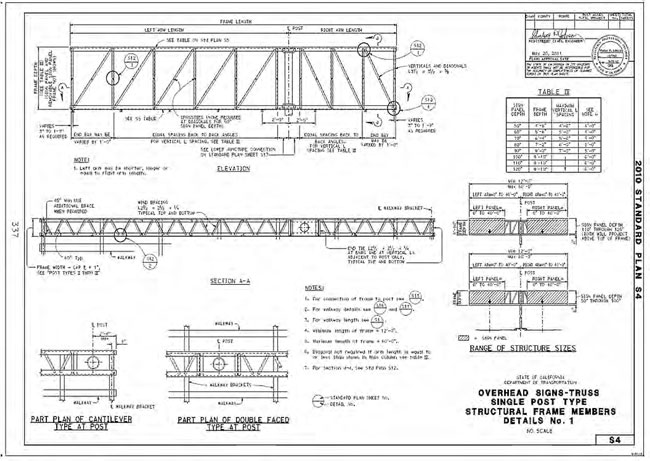
9. Overhead Sign Truss - Single Post Type
Truss frame length, which is the sum of the left and right arm
lengths of the sign structure, range from a minimum 12 feet to a maximum of 60 feet. Standard Plan S4 show
details for the placement of sign panels on the sign structure (left and right sides) as well as minimum and
maximum length of the panels (0 feet and 40 feet, respectively). Table IV of Standard Plan S4 show truss frame
depth and maximum vertical spacing, L, as a function of sign panel depth (ranges from 50 inches to 120 inches).
2010 Standard Plan S4 - Overhead Signs-Truss Single Post Type Structural Frame Members Details No. 1.
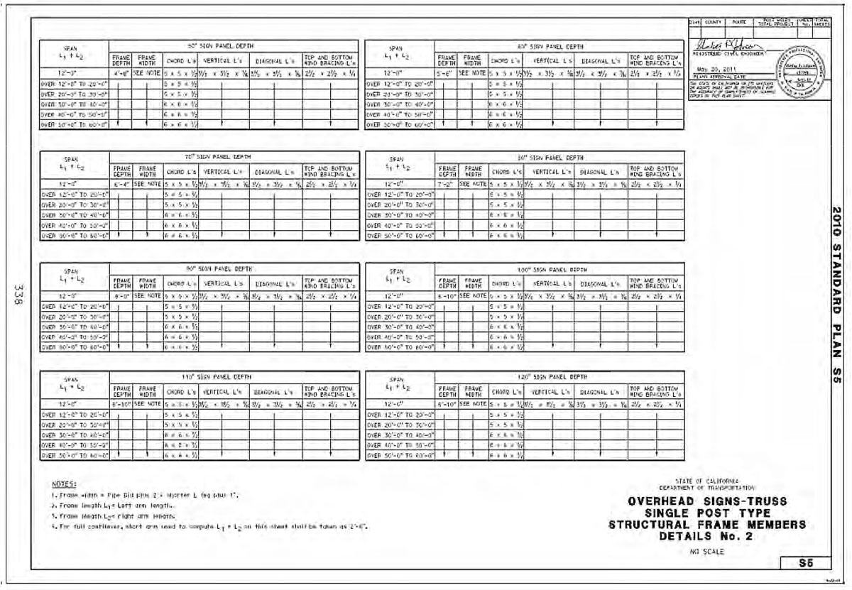
10. Standard Plan S5
Outline details as to the structural connection and spacing of vertical, horizontal and diagonal elements of the truss as a function of frame length and sign panel depth.
2010 Standard Plan S5 - Overhead Signs-Truss Single Post Type Structural Frame Members Details No. 2.
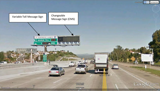
11. Photos
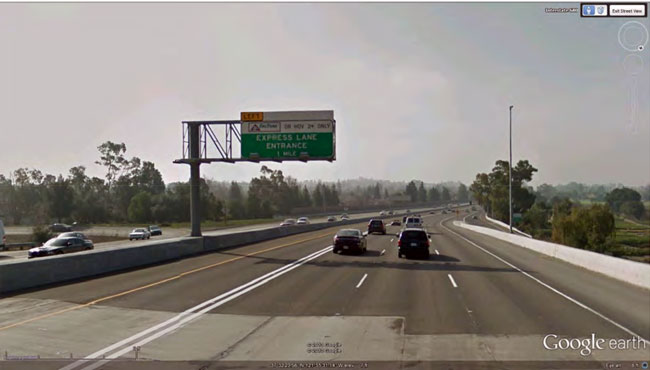
Photo 11A - Variable Tolling Message Sign and CMS mounted on single post overhead truss sign structure along I-15 freeway in San Diego. Photo 11B
- Express Lane Entrance warning sign mounted on single post overhead truss sign structure along I-680 in Milpitas, CA.


![Figure B-1D — Key Map of Visual Simulations and Photo Documentation (City of Carlsbad [South]). For more information call (619) 688-6670 or email CT.Public.Information.D11@dot.ca.gov](/-/media/dot-media/district-11/images/pwp/app-b/figb-1d.jpg)
![Figure B-1E — Key Map of Visual Simulations and Photo Documentation (City of Carlsbad [North]). For more information call (619) 688-6670 or email CT.Public.Information.D11@dot.ca.gov](/-/media/dot-media/district-11/images/pwp/app-b/figb-1e.jpg)